
Solenoid valve

a solenoid valve and valve body technology, applied in the direction of valve details, valve arrangement, thin material processing, etc., can solve the problems of increasing processing cost and difficult to completely prevent leakage, and achieve the effect of reducing the flow amount and reducing the leakage of the slide member

Active Publication Date: 2012-08-23
EAGLE INDS
View PDF4 Cites 21 Cited by
  • Summary
  • Abstract
  • Description
  • Claims
  • Application Information

AI Technical Summary

Benefits of technology

The present invention provides a small-size solenoid valve with high pressure resistance, able to control flow amount reliably and highly accurately and able to reduce cost. The valve has a unique structure that allows for good sealing and leakage control, while also allowing for easy processing and assembly. The valve has a high pressure resistance, making it suitable for use in hydraulic control of automatic transmissions. The valve is controlled by an electromagnetic force and a mechanical force, and the opening amount is controlled by the force of the solenoid. The valve is supported by a spring and a spring device, which allows for good control characteristics. The valve is also cost-effective and easy to assemble.

Problems solved by technology

In this type of solenoid valves, it is necessary to provide clearance between the sleeve and the spool, so that it is difficult to completely prevent leakage between these two.
As a method for reducing the leakage, the following solutions can be considered such that a length of a sliding portion is made longer, or such that clearance is made very small, which require highly accurate processing to result in growing processing cost.

Method used


Image

  • Solenoid valve
  • Solenoid valve
  • Solenoid valve

Examples


first embodiment

[0023]The first embodiment of the present invention will be explained in reference to FIG. 1.

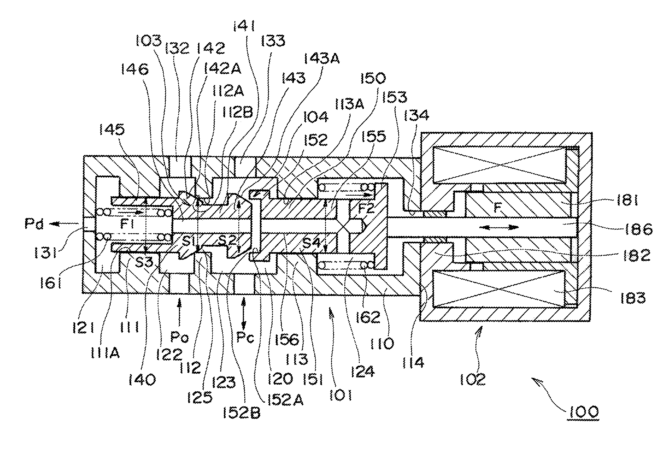
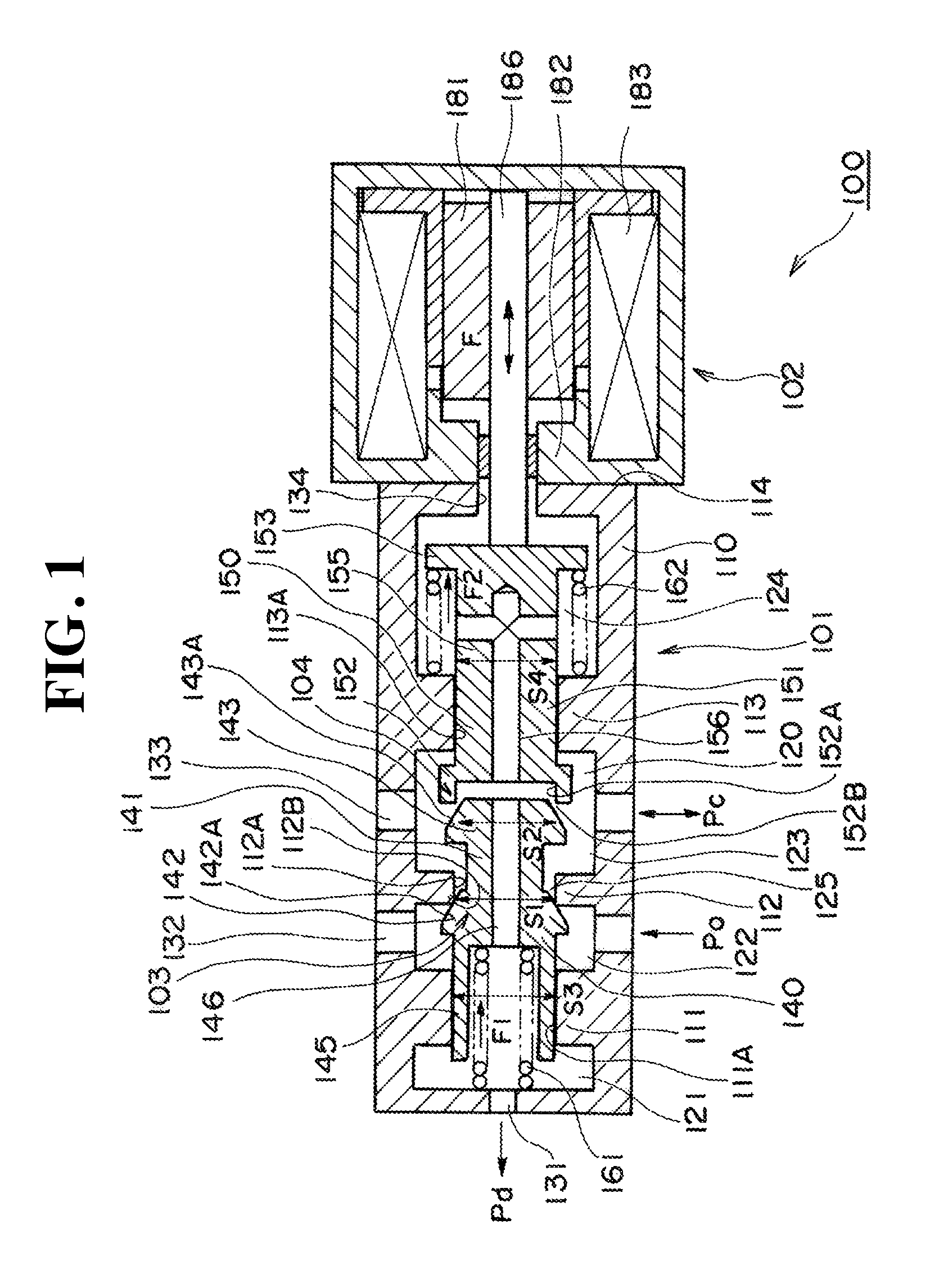
[0024]In the present embodiment, basic constitution of a normal close-type solenoid valve according to the present invention will be explained in reference to FIG. 1. The solenoid valve of the present embodiment can be used for hydraulic brake and the like of automatic transmission, for example.

[0025]FIG. 1 is a cross-sectional view of a solenoid valve 100 according to the present invention.

[0026]As shown in FIG. 1, the solenoid valve 100 is obtained by integrally forming a control valve portion 101 and a solenoid portion 102.

[0027]The control valve portion 101 has a body 110 as an outer frame and a valve space chamber 120 penetrating inside the body 110 in axial direction. The valve space chamber 120 is divided by a first to third partition portions 111 to 113 to separate into a first pressure-sensing chamber 121, a first valve chamber 122, a second valve chamber 123 and a second pressure-s...

second embodiment

[0089]The second embodiment of the present invention will be explained in reference to FIG. 2.

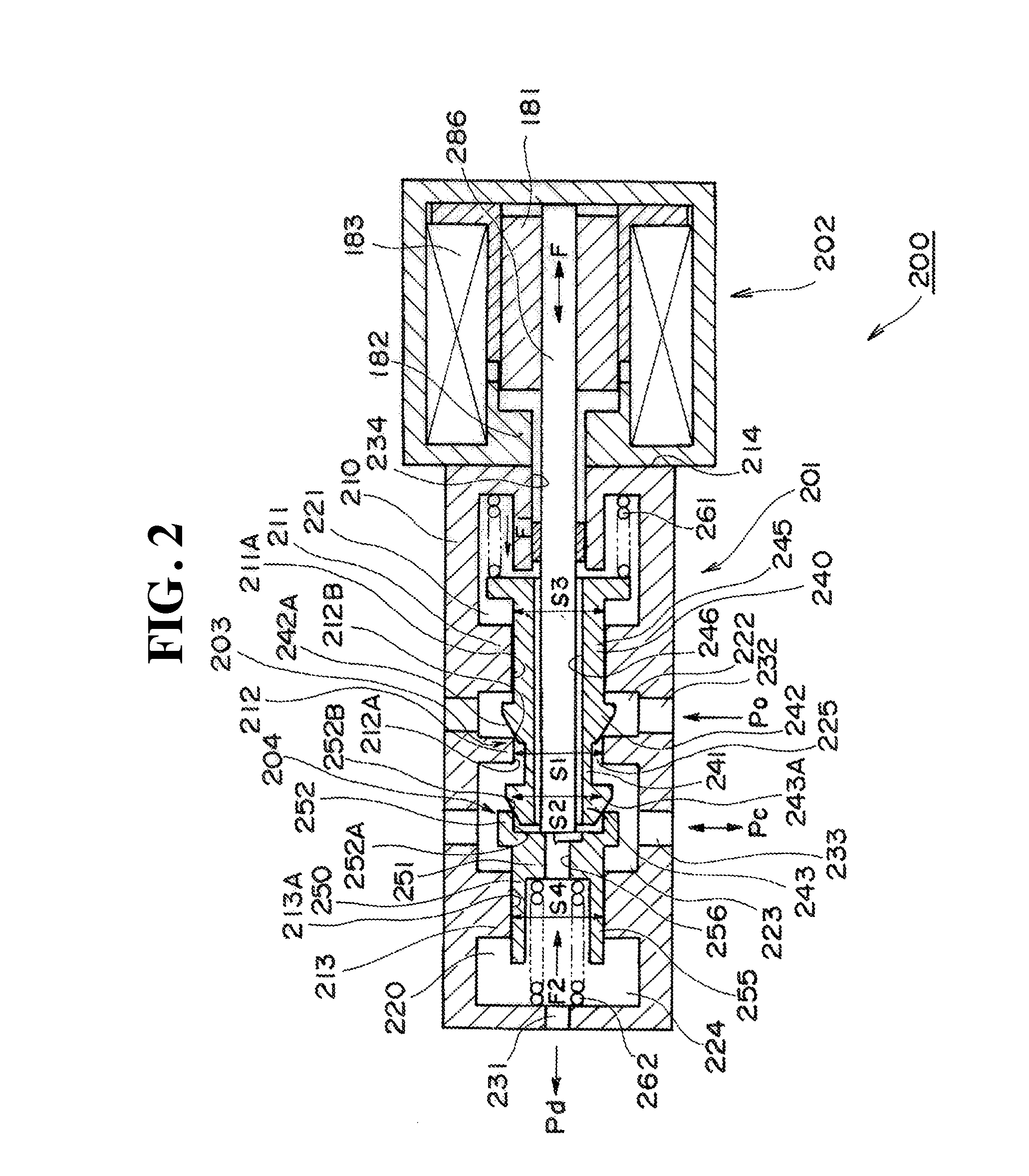
[0090]In the present embodiment, basic constitution of a normal open-type solenoid valve according to the present invention will be explained in reference to FIG. 2. The solenoid valve of the present embodiment, as with the first embodiment, can be used for hydraulic brake and the like of automatic transmission, for example.

[0091]FIG. 2 is a cross-sectional view of a solenoid valve 200 according to the present invention.

[0092]As shown in FIG. 2, the solenoid valve 200 is obtained by integrally forming a control valve portion 201 and a solenoid portion 202.

[0093]The control valve portion 201 has a body 210 as an outer frame, and a valve space chamber 220 penetrating inside the body 210 in axial direction. The valve space chamber 220 is divided by a first to third partition portions 211 to 213 to separate into a first pressure-sensing chamber 221, a first valve chamber 222, a second valve cha...

third embodiment

[0148]The third embodiment of the present invention will be explained in reference to FIG. 3.

[0149]The solenoid valve of the present embodiment is an example of components for achieving the normal close-type solenoid valve according to the present invention shown schematically in FIG. 1.

[0150]Consequently, a solenoid valve 300 of the third embodiment shown in FIG. 3 basically has the same structure of the solenoid valve 100 of the first embodiment, so that the same symbols are assigned to the substantially same components, and explanation thereof is left out.

[0151]In the solenoid valve 300 of the present embodiment, a body 310 is, for the reason of assembling, divided into a first body portion 311, a second body portion 312 and a third body portion 313 in the order from the solenoid portion 102 side, in which the respective end portions are provided with screw portions. The body 310 is integrally assembled by screwing the corresponding screw portions.

[0152]Also, for the second parti...


PUM


Abstract

The present invention provides a solenoid valve able to control flow amount as desired without receiving influence of change in fluid pressure. In the present invention, in a control valve for opening and closing a first poppet valve 103 and a second poppet valve 104 by a solenoid portion, a first pressure receiving area S1 which is a seating area of the first poppet valve 103, a second pressure receiving area S2 which is a seating area of the second poppet valve 104, a third pressure receiving area S3 which is a pressure receiving area of a first pressure sensing portion 145 and a fourth pressure receiving area S4 which is a pressure receiving area of a second pressure sensing portion 155 are made approximately equal to each other. Thereby unbalanced forces received from fluid flowing in and out when each poppet valve is actuated are all canceled.

Description

TECHNICAL FIELD[0001]The present invention relates to a solenoid valve used for, for example, hydraulic control and the like of an automatic transmission.BACKGROUND ART[0002]A spool valve type solenoid valve is widely used, wherein a spool is slidably set up along an inner circumferential surface of a sleeve in which a port is formed on a side face thereof and a position of the spool is controlled by an electromagnetic force by solenoid and a mechanical force of a spring and the like; and the pressure of working fluid is controlled thereby. In this type of solenoid valves, it is necessary to provide clearance between the sleeve and the spool, so that it is difficult to completely prevent leakage between these two. As a method for reducing the leakage, the following solutions can be considered such that a length of a sliding portion is made longer, or such that clearance is made very small, which require highly accurate processing to result in growing processing cost.[0003]As a solut...

Claims


Application Information

Patent Timeline
Patent Type & Authority Applications(United States)
IPC IPC(8): F16K31/06F16K11/07
CPCF16K31/0624Y10T137/86702Y10T137/8671Y10T137/86919Y10T137/87217
Inventor OKAMOTO, EIJI
Owner EAGLE INDS
Learn More