
Blind rivet

Inactive Publication Date: 2012-08-23
NEWFREY
View PDF12 Cites 11 Cited by
  • Summary
  • Abstract
  • Description
  • Claims
  • Application Information

AI Technical Summary

Benefits of technology

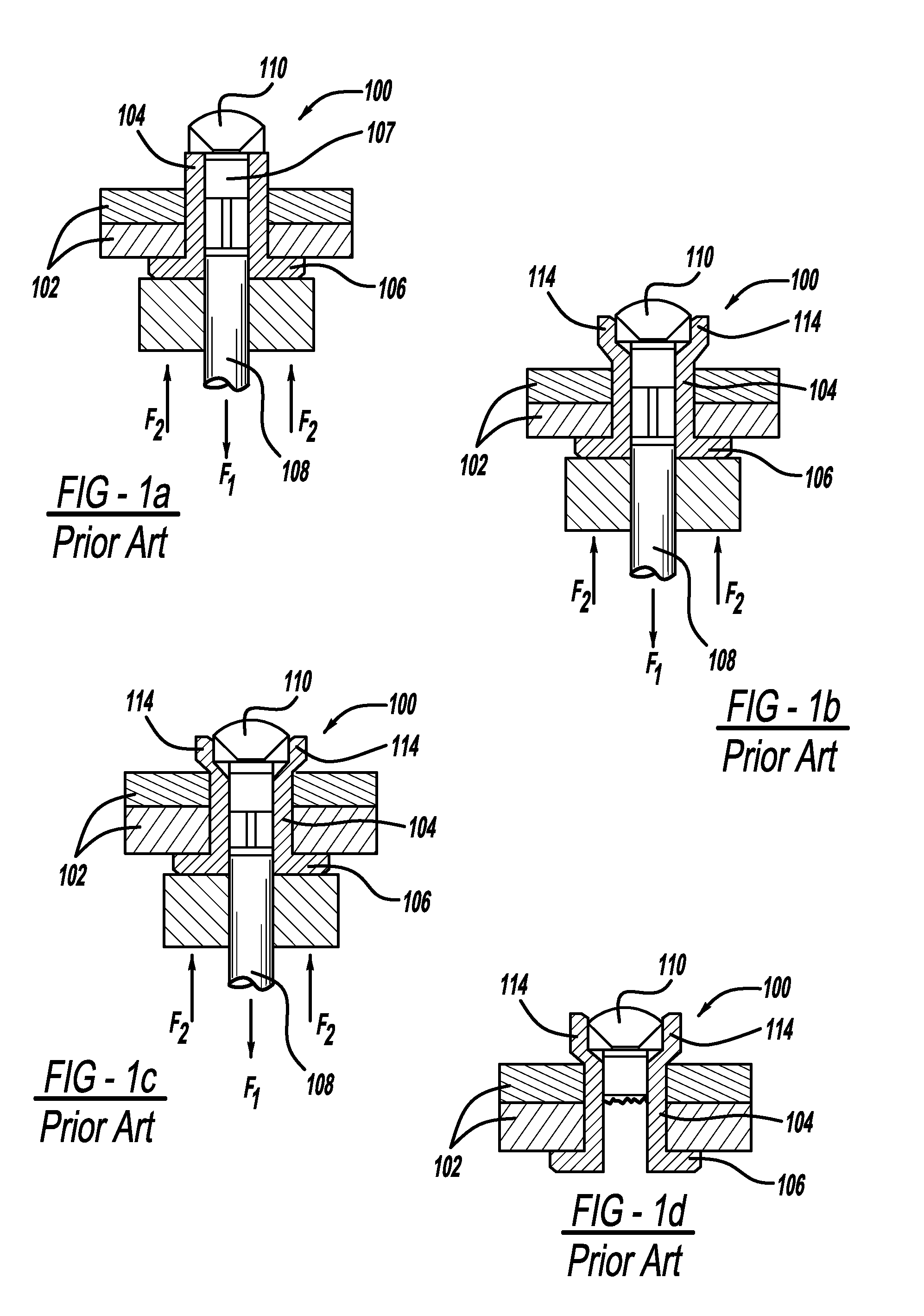
[0003]Manufacturing processes such as automotive manufacturing processes use blind rivets as a means of joining parts together since this is a cost effective method avoiding costly and labour intensive tasks which arise when nut and bolt or screw fastenings are used. Blind rivets, which are well known in the art, are used to attach two pieces of material together by means of access to one side of the material. FIGS. 1a-d illustrate a blind rivet 100, known as a break stem rivet, used to join together two pieces of material 102. The blind rivet 100 has a cylindrical rivet body portion 104 with a flange 106 at one end. A mandrel 107, which has an elongated mandrel stem 108 and a head portion 110 at one end, is fed through the rivet body portion 104 such that the head portion 110 of the mandrel 107 engages the opposite end of the rivet body portion 104 to that from which the flange 106 extends.
[0012]The use of a deformable mandrel head provides the advantage that a blind rivet can be used to fixably attach pieces of material together having dissimilar sized apertures extending therethrough. In another preferred embodiment said mandrel head has a tapering cross section. In a preferred embodiment said mandrel head has a substantially part-conical cross-section. This allows the mandrel head to slightly enter the rivet body portion prior to its deformation providing the advantage that the rivet body portion is evenly deformed around the aperture extending through it.
[0013]In a further preferred embodiment said elongated portion has a plurality of first ribs arranged on an outer surface thereof for engaging an aperture in a work piece. This increases the grip of the rivet on the work piece thereby providing the advantage of minimizing rotation of the work piece relative to the rivet and vice versa. In a preferred embodiment a plurality of said first ribs extends substantially parallel to a longitudinal axis of said elongated portion.
[0014]In another preferred embodiment said flange has a plurality of second ribs arranged thereon for engaging an edge of an aperture in a work piece. This increases the grip of the rivet on the work piece thereby providing the advantage of minimizing rotation of the work piece relative to the rivet and vice versa. In a further preferred embodiment a plurality of said second ribs extend transversely to a longitudinal axis of said elongated portion. In a preferred embodiment said bore extends the entire length of said elongated portion.

Problems solved by technology

A problem with conventional break stem and pull through blind rivets, however, is that it is difficult to reliably join pieces of material having dissimilar sized apertures extending therethrough.
This complicates and increases the cost of a manufacturing process.

Method used


Image

  • Blind rivet
  • Blind rivet
  • Blind rivet

Examples


Embodiment Construction

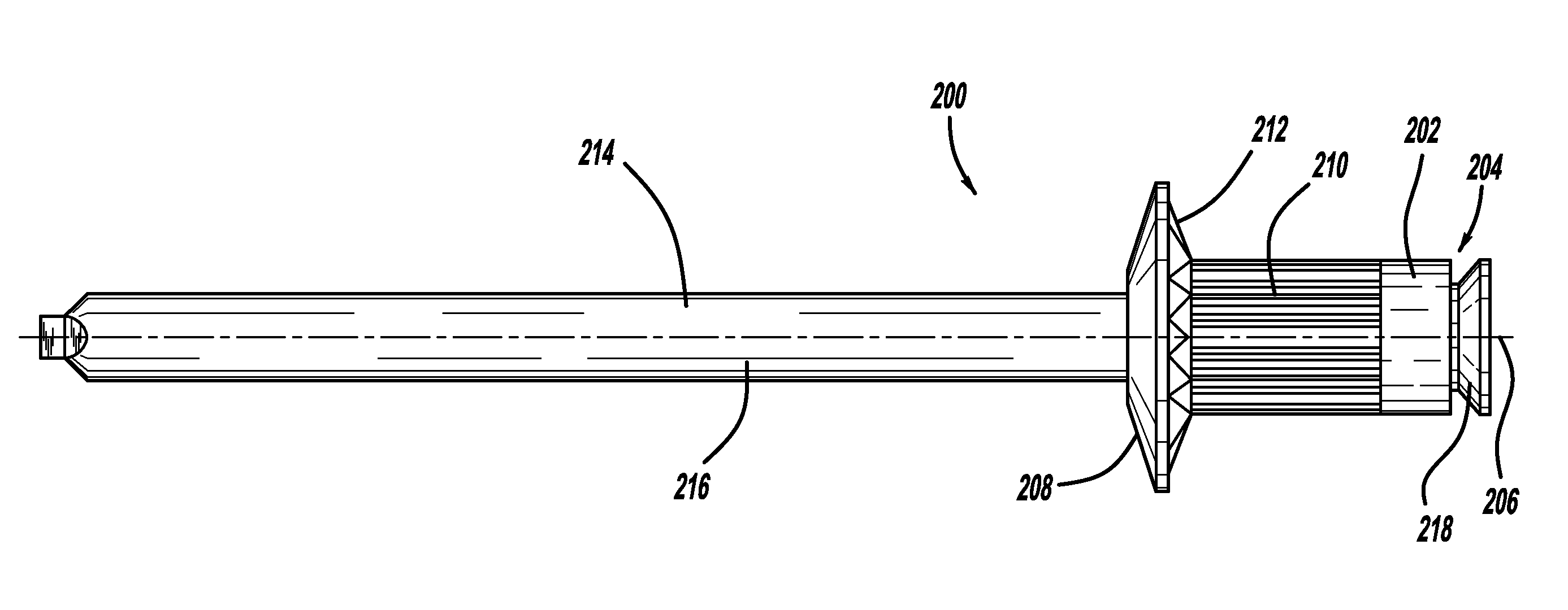
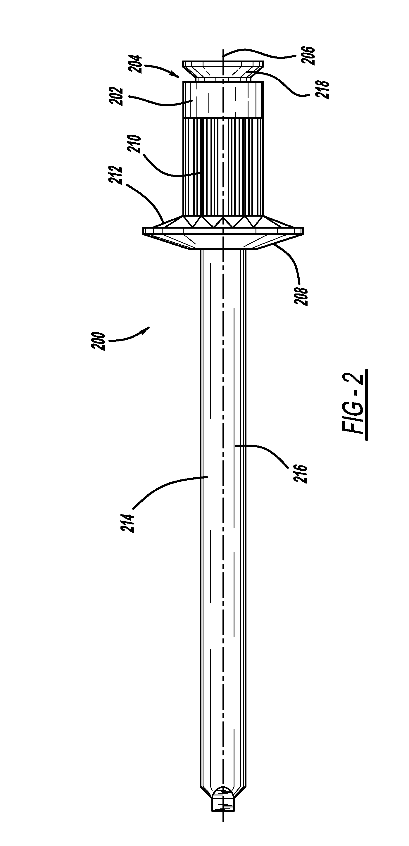
[0020]FIG. 2 illustrates a pull through blind rivet 200 embodying the present invention. The blind rivet 200 has a cylindrical rivet body portion 202 having a bore 204 extending entirely through it along an axis 206. The rivet body portion 202 has a flange portion 208 extending from it at one end, and has a partially ribbed outer surface 210. The flange portion 208 also has a ribbed surface 212 on the side of the flange facing the direction of the rivet body portion 202. A mandrel 214 having an elongated mandrel stem 216 and a deformable mandrel head 218 extends through the bore 204 in the rivet body portion 202. The mandrel head 218 is wider than the bore 204 extending through the rivet body portion 202. The mandrel is secured to the rivet body prior to setting by an interference fit between the stem and the bore of the rivet body.

[0021]The operation of the blind rivet 200 in FIG. 2, will now be described with reference to FIG. 3. As shown in FIG. 3a, the pieces of material 220, 22...


PUM

PropertyMeasurementUnit
Thicknessaaaaaaaaaa
Sizeaaaaaaaaaa
Distanceaaaaaaaaaa

Abstract

A blind rivet 200 comprises a mandrel 214 having a deformable mandrel head 218 such that when the blind rivet is received in a pair of aligned apertures of dissimilar sizes in a pair of components 220, 222 to be joined, the mandrel head is adapted to be deformed and cause deformation of a rivet body 202 such that the blind rivet engages the inner surfaces defined by both of the apertures before the mandrel and its head are pulled free of the rivet body.

Description

CROSS-REFERENCE TO RELATED APPLICATIONS[0001]This application claims the benefit of U.S. Provisional Application No. 61 / 236,270, filed on Aug. 24, 2009, which is incorporated by reference herein.BACKGROUND AND SUMMARY[0002]The present invention relates to blind rivets, and relates particularly to a blind rivet having a mandrel with a deformable mandrel head.[0003]Manufacturing processes such as automotive manufacturing processes use blind rivets as a means of joining parts together since this is a cost effective method avoiding costly and labour intensive tasks which arise when nut and bolt or screw fastenings are used. Blind rivets, which are well known in the art, are used to attach two pieces of material together by means of access to one side of the material. FIGS. 1a-d illustrate a blind rivet 100, known as a break stem rivet, used to join together two pieces of material 102. The blind rivet 100 has a cylindrical rivet body portion 104 with a flange 106 at one end. A mandrel 10...

Claims


Application Information

Patent Timeline
IPC IPC(8): B21J15/02F16B13/06F16B13/08F16B19/08
CPCB21J15/043Y10T29/49956F16B19/1045B21J15/365
Inventor JONES, STEVEN V.SMITH, DANIEL R.
Owner NEWFREY
Learn More