
Separatorless pleated fluid filter

a technology of fluid filter and separator, which is applied in the direction of separation process, filtration separation, transportation and packaging, etc., can solve the problem that the filter medium may not include a separator

Active Publication Date: 2012-08-16
JOHNS MANVILLE CORP
View PDF7 Cites 3 Cited by
  • Summary
  • Abstract
  • Description
  • Claims
  • Application Information

AI Technical Summary

Benefits of technology

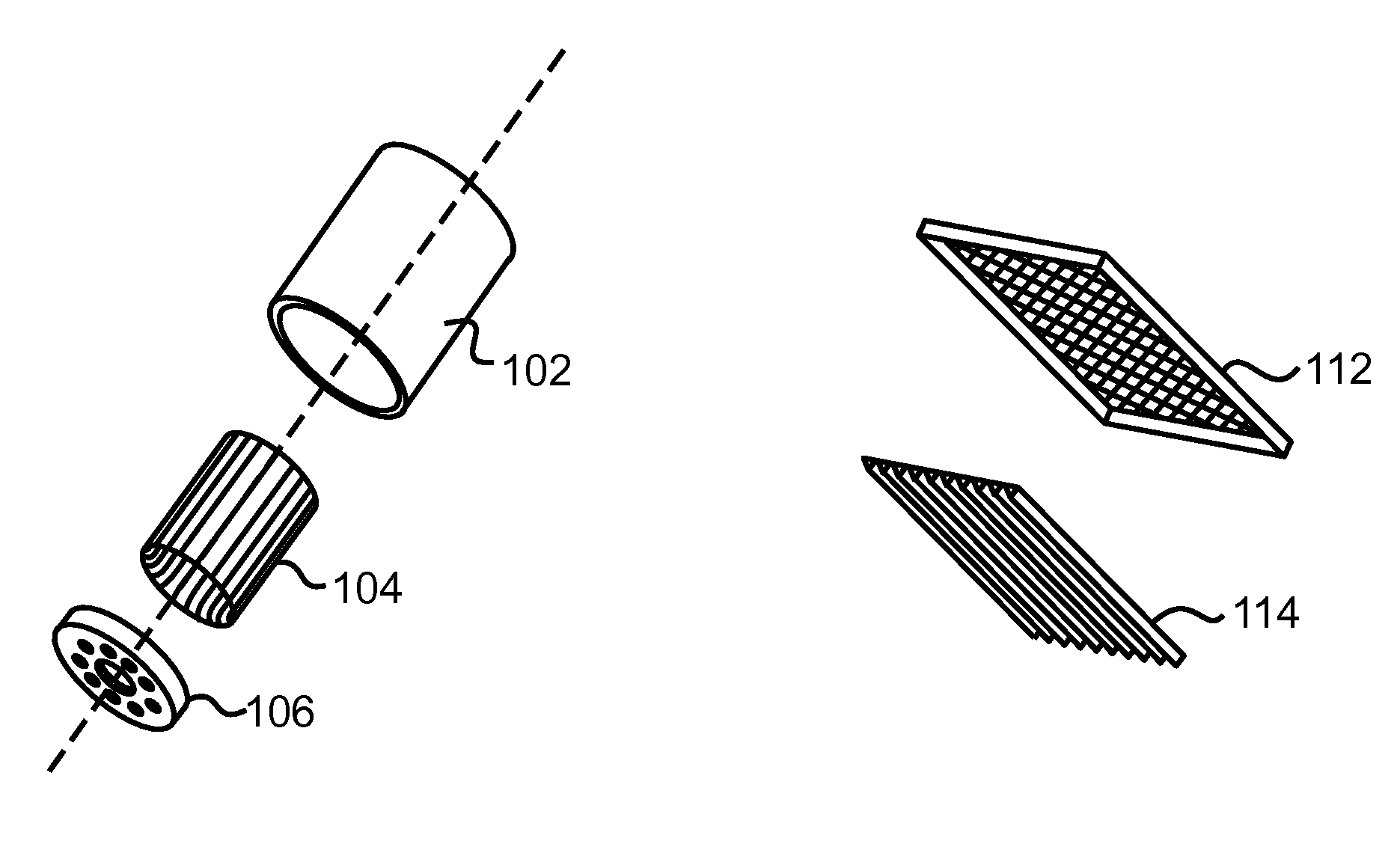
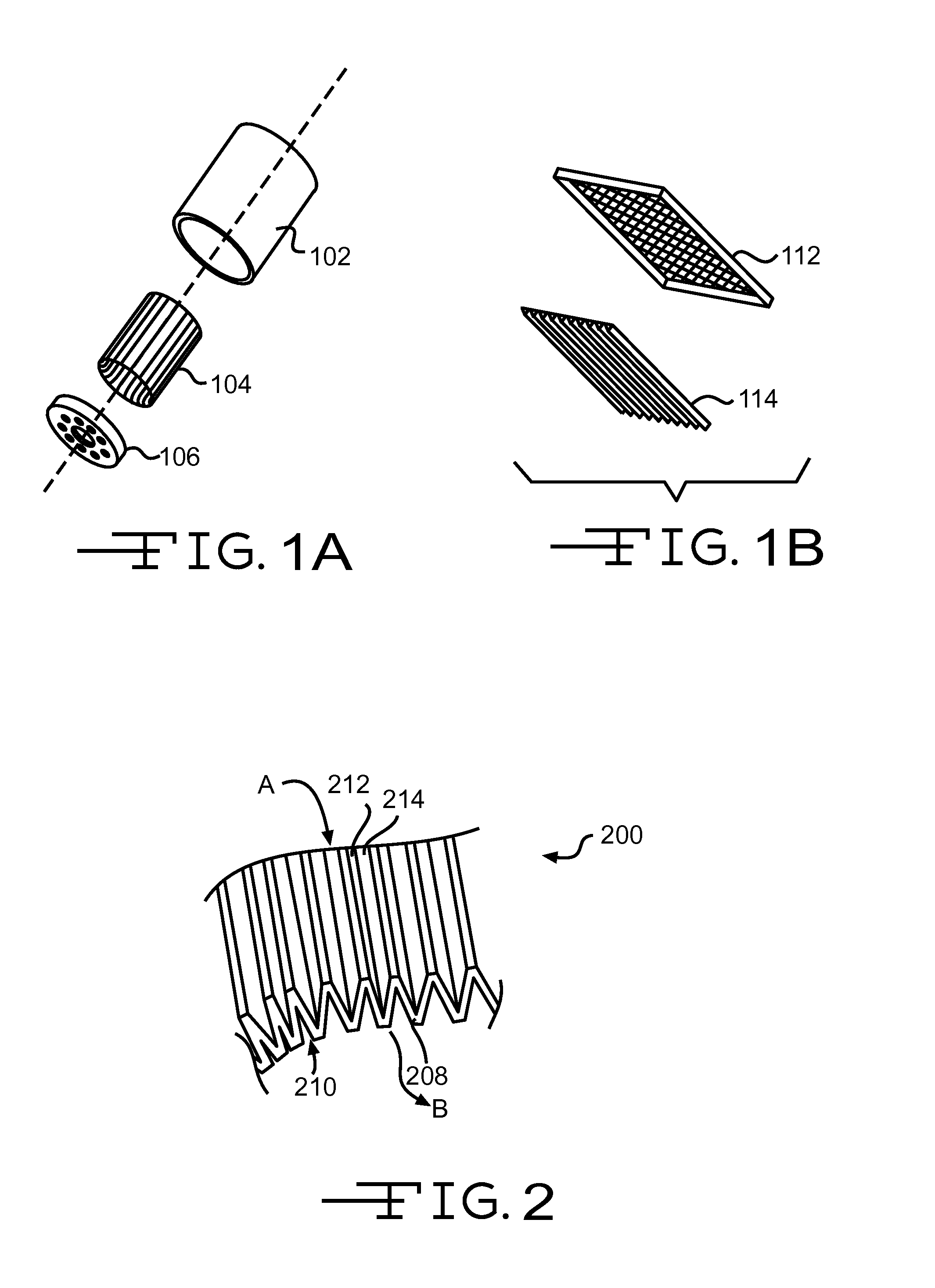
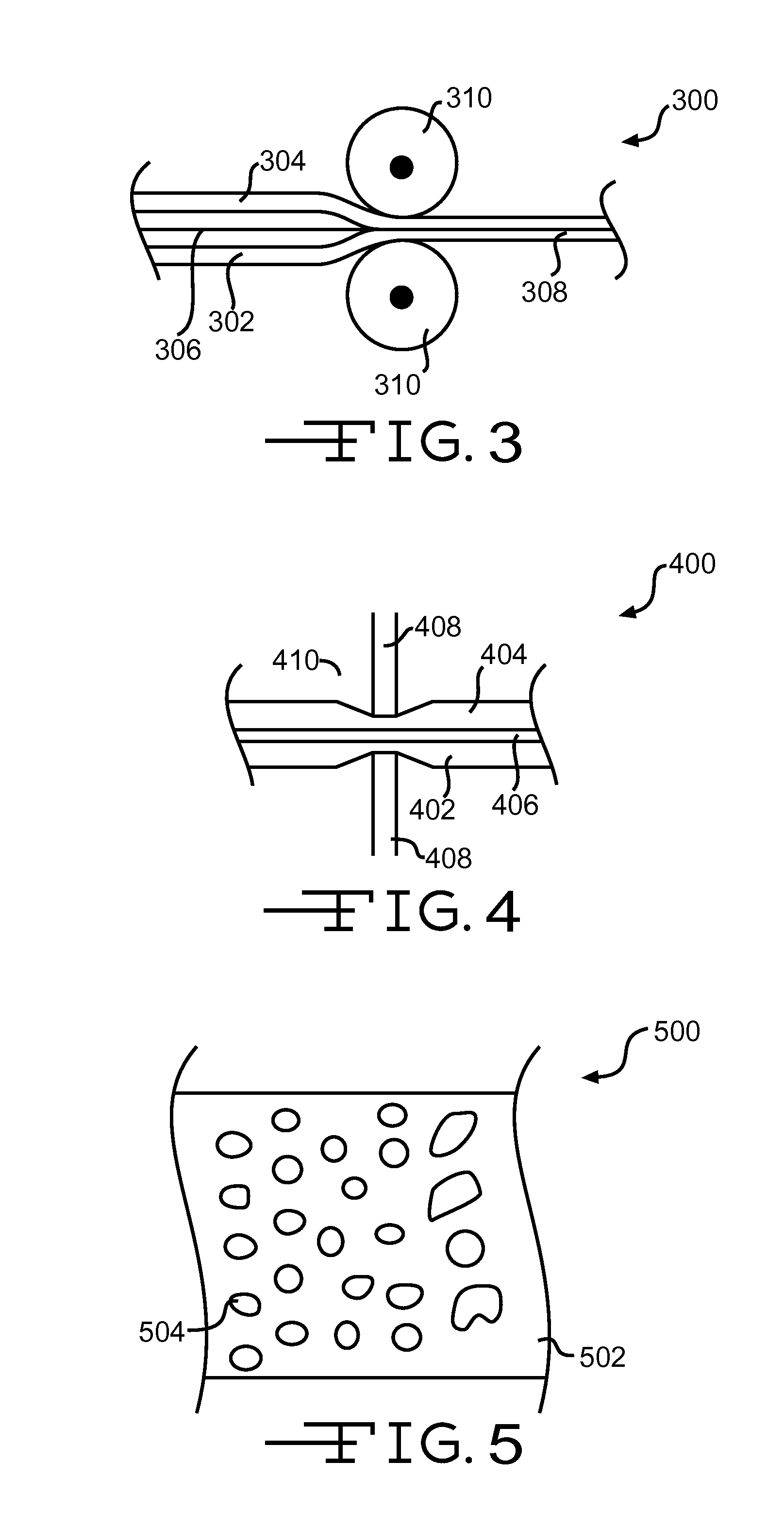
[0011]According to a further embodiment, a method of making a filter medium that removes one or more particles from a fluid passed through the filter medium may include providing a first media layer, providing a second media layer, providing a filter layer, positioning the filter layer between the first media layer and the second media layer, coupling the first media layer with the second media layer at a plurality of spaced apart weld points to form the filter medium, and folding the filter medium back on itself to form a plurality of pleats in the filter medium. The weld points may distort the surface of the first media layer and the second media layer and the surface distortions may permit fluid flow through the filter medium when adjacent surfaces of the filter medium are touching. The pleated filter medium may be formed to be hollow and cylindrical shape with the first media layer on the exterior of the cylindrical filter medium and the second media layer on the interior of the cylindrical filter medium and the method may further include providing a cylindrical container having an interior, an open end, and a closed end, and assembling the cylindrical container with the cylindrical filter medium by axially aligning the cylindrical container and the cylindrical filter medium and by positioning the cylindrical filter medium within the interior of the cylindrical container.

Problems solved by technology

Furthermore, the surface distortions may permit fluid flow through the filter medium when adjacent surface of the filter medium are touching.
In addition, the filter medium may not include a separator to separate adjacent surfaces of the filter medium.

Method used


Image

  • Separatorless pleated fluid filter
  • Separatorless pleated fluid filter
  • Separatorless pleated fluid filter

Examples


Embodiment Construction

[0023]The present invention provides a fluid filter medium that when made into a filter device, filters one or more fluids to remove particles and debris (i.e., contaminants) from the fluid as the fluid is passed through the fluid filter medium. The fluid filter medium may include a housing or container in which the filter medium is positioned. The filter medium may include a first media layer and a second media layer. Additionally, the filter medium may include a third media layer disposed between the first and second media layers. The first and / or second media layers may be constructed of stiff or rigid materials such as paper, polyesters (e.g., spunbond), polypropylene (e.g., Meltblown), etc. The first and / or second media layers may provide structural support for the filter medium and / or may filter one or more types of particles, such as coarse or large materials (e.g., dirt). The first and / or second media layers may additionally or alternatively be constructed of a finer materia...


PUM

PropertyMeasurementUnit
cylindrical shapeaaaaaaaaaa
porosityaaaaaaaaaa
permeabilityaaaaaaaaaa

Abstract

A fluid filter media including a first media layer, a second media layer, a filter layer disposed between the first media layer and the second media layer, and a plurality of spaced apart weld points that couple the first media layer, the filter layer, and the second media layer together, where the weld points distort the surface of the first media layer and the second media layer, the fluid filter media is folded back on itself to form a plurality of pleats, and the surface distortions permit fluid flow through the fluid filter media when adjacent surfaces of the fluid filter media touch.

Description

BACKGROUND OF THE INVENTION[0001]The subject invention relates generally to fluid filter media products and more specifically to fluid filter media products comprising a pleated fluid filter medium.[0002]Fluid Filters are used in a variety of applications to remove particulates and debris (i.e., contaminants) from fluids. For example, fluid filters are commonly used in machinery (e.g., vehicles, engines, etc.) to filter oil, gas, air, and / or other fluids. For example, most vehicles (e.g., cars, trucks, tractors, etc.) contain an oil filter, gas filter, transmission filter, and air filter that remove contaminants from the oil, gas, transmission fluid, and air. Industrial equipment (e.g., compressors, hydraulics, vacuums, purifiers, etc.) often use fluid filters as well to remove contaminants and / or to purify fluids.[0003]Fluid filters often include a filter medium that is placed in the fluid stream or fluid path so that the fluid is forced to flow through (i.e., pass through) the fil...

Claims


Application Information

Patent Timeline
Patent Type & Authority Applications(United States)
IPC IPC(8): B01D39/00B21D35/00B32B37/06B32B37/02B01D29/00B01D46/52
CPCB01D29/111B01D29/232B01D29/333B01D29/56Y10T29/49906B01D46/0001B01D46/0023B01D46/523B01D2201/12B01D29/58B01D46/62
Inventor KERN, CHARLES FRANCIS
Owner JOHNS MANVILLE CORP
Learn More