Liquid crystal display with color light guide panel

a liquid crystal display and light guide technology, applied in the direction of optical light guides, instruments, nanotechnology, etc., can solve the problems of occupying about 15% of the material cost of requiring a relatively long time to fabricate the color filter substrate, and reducing the cost of fabrication

Inactive Publication Date: 2012-08-09
CPT TECH GRP
View PDF1 Cites 46 Cited by
  • Summary
  • Abstract
  • Description
  • Claims
  • Application Information

AI Technical Summary

Benefits of technology

[0018]Since the color light output structure having the first, the second and the third nano-patterns is applied, and the color light output structure can be disposed on the light guide panel, the active device array substrate or the opposite substrate for differentiating the incident light into multiple color lights, the conventional color filter substrate is unnecessary, so that fabrication cost is reduced. Moreover, the primary colors can be individually obtained by controlling the shape, size and arrangement period of the nano particles, so as to achieve a full color display effect.

Problems solved by technology

Moreover, material cost of the color filter substrate occupies about 15% of that of the LCD panel, and a relatively long time is required to fabricate the color filter substrate.
Generally, if the response speed of the liquid crystal is not quick enough, it can be an obstacle for the color sequential technique.
Moreover, to improve the color separation, a complicated control algorithm and a powerful circuit driving capability are required, so that it is hard to be implemented.
However, since requirement for alignment accuracy of the transparent gratings and the pixels is relatively high, it is hard to be fabricated.

Method used


Image

  • Liquid crystal display with color light guide panel
  • Liquid crystal display with color light guide panel
  • Liquid crystal display with color light guide panel

Examples


Embodiment Construction

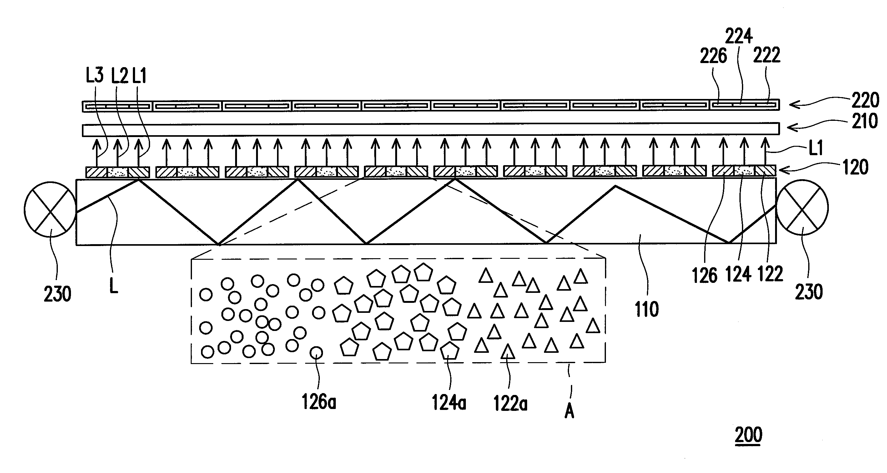
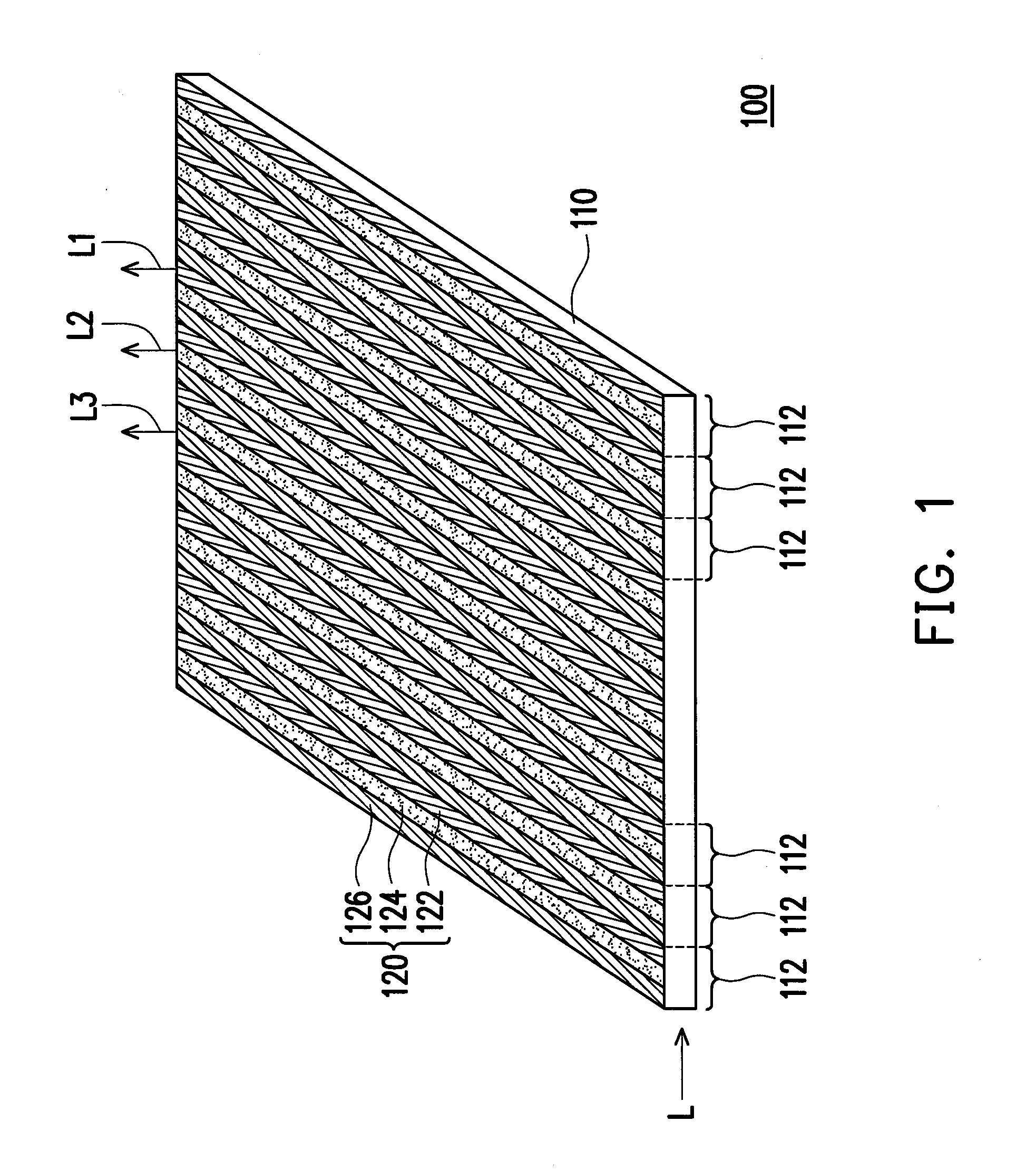
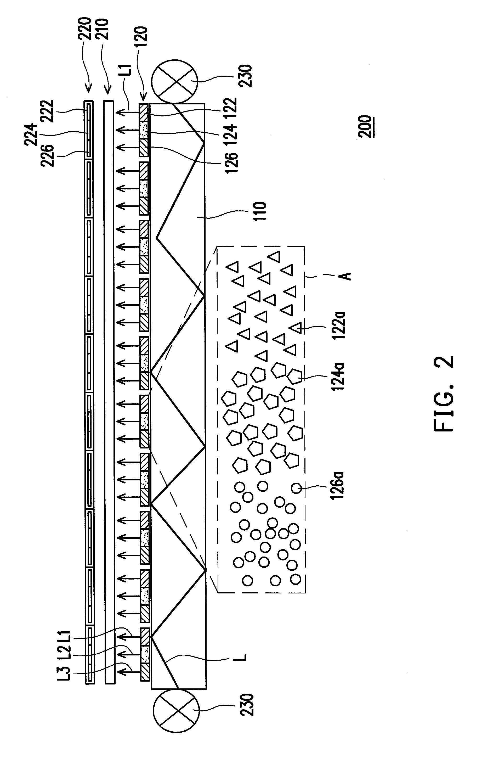
[0027]FIG. 1 is a schematic diagram illustrating a color light guide panel according to a preferred embodiment of the present invention. Referring to FIG. 1, the color light guide panel 100 is suitable for differentiating an incident light L into multiple color lights. The color light guide panel 100 includes a substrate 110 and a color light output structure 120. The substrate 110 has a plurality of pixel regions 112. The color light output structure 120 is disposed in each of the pixel regions 112. The color light output structure 120 includes a first nano-pattern 122, a second nano-pattern 124 and a third nano-pattern 126. The incident light L is scattered by the first nano-pattern 122 for producing a first color light L1, scattered by the second nano-pattern 124 for producing a second color light L2, and scattered by the third nano-pattern 126 for producing a third color light L3.

[0028]Referring to FIG. 1 again, material of the substrate 110 can be glass or transparent resin, wh...


PUM

PropertyMeasurementUnit
diameteraaaaaaaaaa
Diametersaaaaaaaaaa

Abstract

An LCD including a backlight module and an LCD panel is provided. The LCD panel includes a color light guide panel, suitable for differentiating an incident light into multiple color lights. The color light guide panel includes a substrate and a color light output structure. The substrate has multiple pixel regions, and the color light output structure is disposed in each of the pixel regions. The color light output structure includes first˜fourth nano-patterns. The incident light is scattered by the first nano-pattern for producing a first color light, scattered by the second nano-pattern for producing a second color light, scattered by the third nano-pattern for producing a third color light, and scattered by the fourth nano-pattern for producing a fourth color light. The color light guide panel can output uniform and high luminous first˜fourth color light, and the LCD can display high quality image.

Description

CROSS-REFERENCE TO RELATED APPLICATION[0001]This application is a divisional application of and claims the priority benefit of U.S. patent application Ser. No. 12 / 315,127, filed on Nov. 26, 2008, now pending, which claims the priority benefit of Taiwan application serial no. 97124571, filed Jun. 30, 2008. The entirety of each of the above-mentioned patent applications is hereby incorporated by reference herein and made a part of this specification.BACKGROUND OF THE INVENTION[0002]1. Field of the Invention[0003]The present invention relates to a light guide panel and a display device. More particularly, the present invention relates to a color light guide panel and a liquid crystal display (LCD) having a color light output structure.[0004]2. Description of Related Art[0005]With development of the photoelectric technology and the semiconductor technology, flat panel displays (FPD) such as LCDs gradually become popular in the market. Generally, the LCD includes a backlight module and a...

Claims


Application Information

Patent Timeline
Patent Type & Authority Applications(United States)
IPC IPC(8): G02F1/1335
CPCG02B6/0043Y10S977/952G02F1/133621
Inventor WEI, PEI-KUENYAO, YEONG-DERWEI, DA-HUAHSU, SHEN-YUCHENG, KAI-WENLIN, TZU-PINMO, CHI-NENG
Owner CPT TECH GRP
Why Eureka
Try Eureka