
Locator beacon wireless health monitor

a wireless health monitor and locator beacon technology, applied in the field of electronic devices, can solve the problems of affecting the service interval of the fdr, affecting the service life of the fdr, and most of the fdr chassis and inner components may be damaged,

Active Publication Date: 2012-08-09
L3 TECH INC
View PDF2 Cites 26 Cited by
  • Summary
  • Abstract
  • Description
  • Claims
  • Application Information

AI Technical Summary

Problems solved by technology

In the event of a crash, most of the FDR chassis and inner components may be damaged.
In contrast, a locator beacon external to the FDR may be susceptible to g-forces of the impact, heat of ensuing fire, submersion, and other environmental conditions.
The locator beacon and / or battery must be replaced periodically because FDRs have no means of monitoring the charge state of the battery or to recharge the battery.
Thus, the service interval of the FDR is in part limited by the locator beacon battery.
Despite the advantages of the above described health monitoring techniques of the locator beacon and its battery, they suffer from certain drawbacks.
The location of the beacon may be difficult to access.
Also, the health monitoring of the locator beacon is a manual process, which is relatively time consuming and expensive.

Method used


Image

  • Locator beacon wireless health monitor
  • Locator beacon wireless health monitor
  • Locator beacon wireless health monitor

Examples


second embodiment

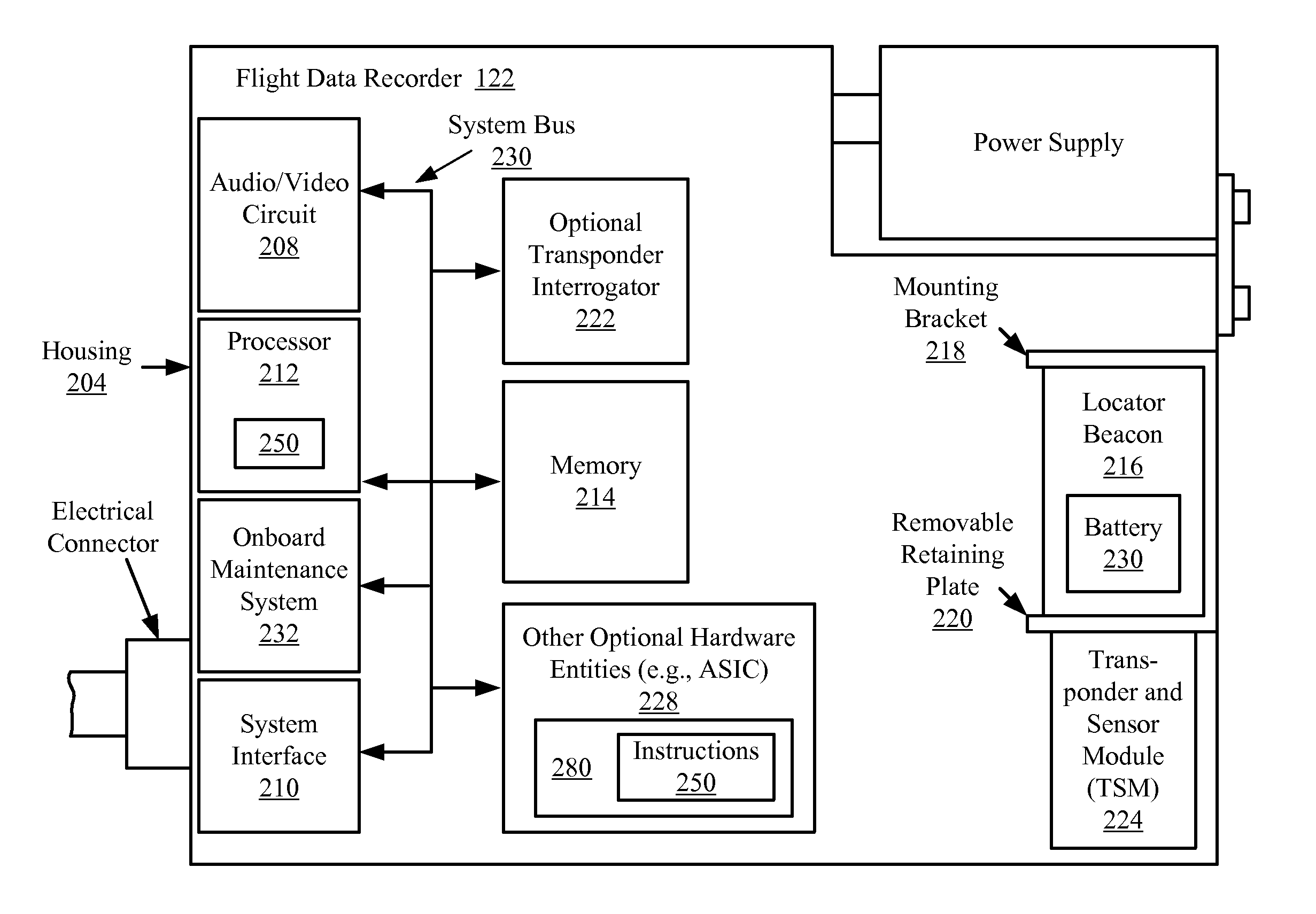
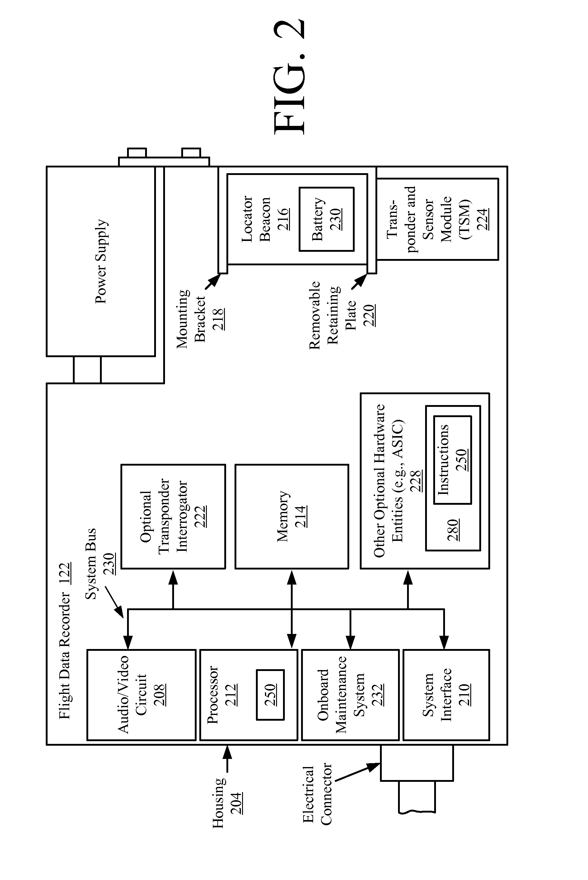
[0059]Referring now to FIG. 6, there is provided a schematic illustration of a second embodiment for coupling the TSM 224 to the locator beacon 216 that is useful for understanding the present invention. As shown in FIG. 6, the TSM 224 comprises at least one flange 602. The flange 602 is coupled to an exposed surface of the retaining plate 220 of the mounting bracket 218 via an adhesive 604 (such as glue or solder). Embodiments of the present invention are not limited in this regard.

third embodiment

[0060]Referring now to FIG. 7, there is provided a schematic illustration of a third embodiment for coupling the TSM 224 to the locator beacon 216 that is useful for understanding the present invention. As shown in FIG. 7, the TSM 224 comprises at least one securing protrusion 704 extending from a bottom surface thereof. The securing protrusion 704 is generally configured for coupling TSM 224 to the locator beacon 216 via retaining plate 220. The securing protrusion 704 is also configured to provide an alignment structure for aligning the negating lead 504 with the water activation switch 302 and the positive lead 502 with the housing surface 304.

[0061]If a single securing protrusion 704 is provided, then the securing protrusion 704 may be a ring shaped protrusion having a diameter, radius and circumference that is slightly smaller than the aperture 406 formed in the retaining plate 220. During operation, the ring-shaped protrusion frictionally engages a surface 704 of the retaining...

fourth embodiment

[0063]Referring now to FIG. 8, there is provided a fourth embodiment for coupling the TSM 224 to the locator beacon 216 that is useful for understanding the present invention. As shown in FIG. 8, the TSM 224 comprises at least two clips 802. The clips 802 have a generally L-shape and is somewhat flexible. During operation, the clips 802 engage an engagement surface 804 of a lip 806 of the retaining plate 220. In this scenario, the retaining plate 220 may need to be modified to include the lip 806. Embodiments of the present invention are not limited in this regard.


PUM


Abstract

Systems (224, 222, 700) and methods (800) for providing wireless health monitoring for a locator beacon (216). The methods involve: coupling a Transponder and Sensor Module (TSM) to the locator beacon such that at least one condition of the locator beacon or a battery (230) of the locator beacon can be remotely monitored; periodically detecting the condition by the TSM (224); and periodically and wirelessly transmitting, from the TSM to a wireless device (222, 700) located in proximity to the TSM, a signal including information describing the condition detected by the TSM. The TSM can include, but is not limited to a transponder (e.g., an RFID tag) and sensor. The wireless device, can include, but is not limited to a transponder interrogator.

Description

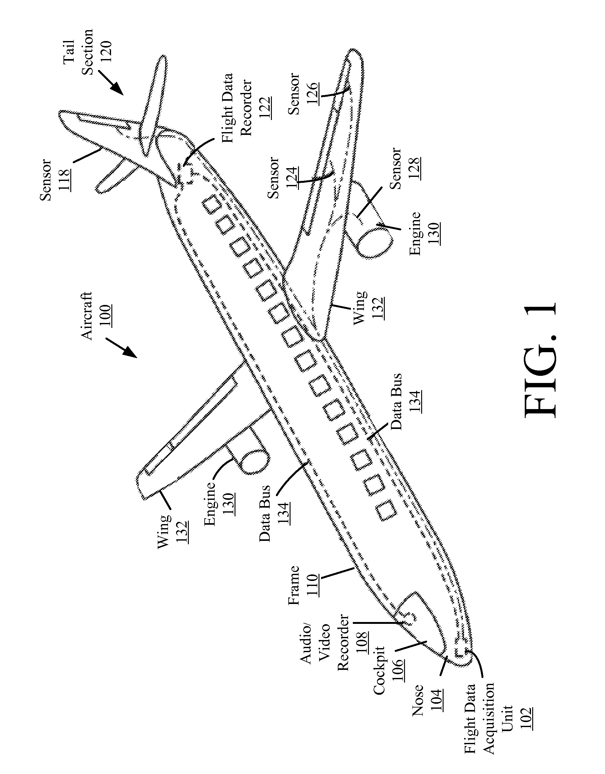
BACKGROUND OF THE INVENTION[0001]1. Statement of the Technical Field[0002]The inventive arrangements relate to electronic devices, and more particularly to systems and method for providing wireless health monitoring for locator beacons and batteries thereof.[0003]2. Description of the Related Art[0004]Most commercial and military aircraft, as well as many civilian aircraft, carry Flight Data Recorders (FDRs) and / or Cockpit Voice Recorders (CVRs). During normal flight operations, the FDR records specific aircraft performance parameters, such as air speed, altitude, vertical acceleration, time, magnetic heading, control-column position, rudder-pedal position, control-wheel position, horizontal stabilizer and fuel flow. The CVR records cockpit voices and other audio such as conversations between ground control and flight crew. Each of the recorders has an enclosure containing an electronic interface, processing circuits and a Crash Survivable Memory Unit (CSMU). The CSMU contains non-v...

Claims


Application Information

Patent Timeline
Patent Type & Authority Applications(United States)
IPC IPC(8): G01S1/00
CPCB64D45/00B64D2045/0065B64D2045/0085Y02T50/53G01S13/756G01S5/0226G01S1/022G01S5/0231Y02T50/50
Inventor WEED, MICHAEL E.BERECZ, ENDRE
Owner L3 TECH INC
Learn More