
System for Measuring Intraocular Pressure

a technology for intraocular pressure and measuring system, which is applied in the field of ocular biometry, can solve the problems of not being able to deduce, not being able to perform regular maintenance (cleaning, hydrating) by the patient, and the manipulation of these lenses by the patient running the risk of damaging the detection and transmission circui

Active Publication Date: 2012-08-02
CESACAR PARTICIPACIONS SL
View PDF29 Cites 11 Cited by
  • Summary
  • Abstract
  • Description
  • Claims
  • Application Information

AI Technical Summary

Benefits of technology

[0018]A further aim is to retain the regular external surface of the eye, for example, to make the wearing of corrective corneal lenses possible.

Problems solved by technology

In addition, occasional measurements (spaced out in time) do not make it possible to deduce, from the pressure measured, arterial pressure at the level of the optic nerve.
A drawback of using corneal lenses is that they need regular maintenance (cleaning, hydrating) by the patient.
On the one hand, manipulation of these lenses by the patient runs the risk of damaging the detection and transmission circuits.
On the other hand, a mistake in maintenance may falsify the measurements.
Another drawback of using corneal lenses is that it prevents the patient wearing vision corrective lenses.
These limitations mean that it is difficult to obtain a continuous measurement over a relatively long period (several days) without interruption.
Another drawback of corneal lenses is that the measurements are often highly affected by noise, which limits resolution in the possible exploitation of the measurements.

Method used


Image

  • System for Measuring Intraocular Pressure
  • System for Measuring Intraocular Pressure
  • System for Measuring Intraocular Pressure

Examples


Embodiment Construction

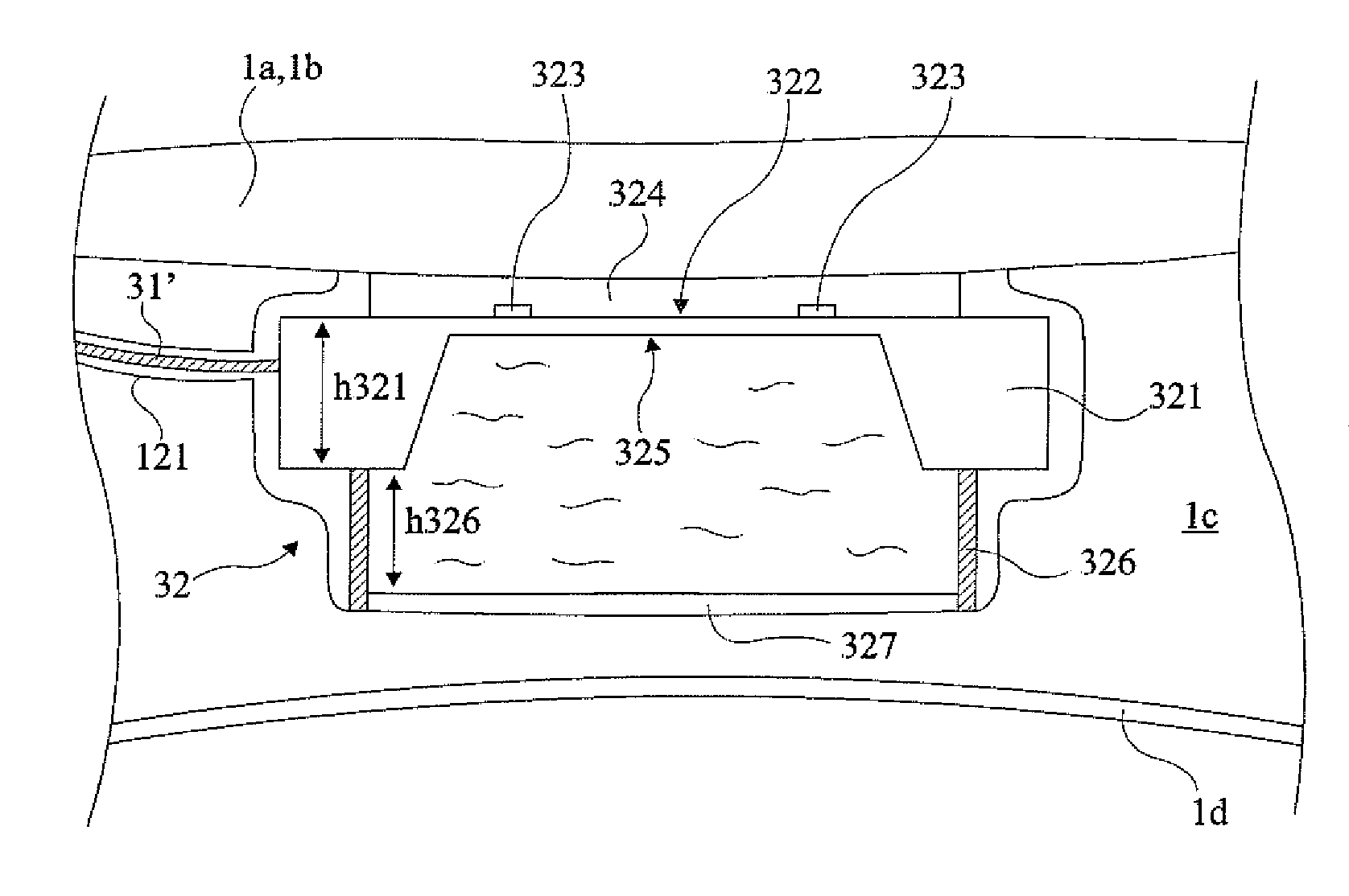
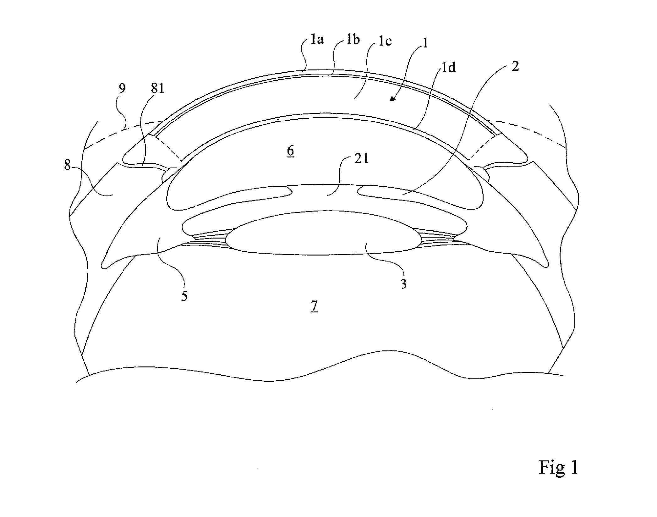
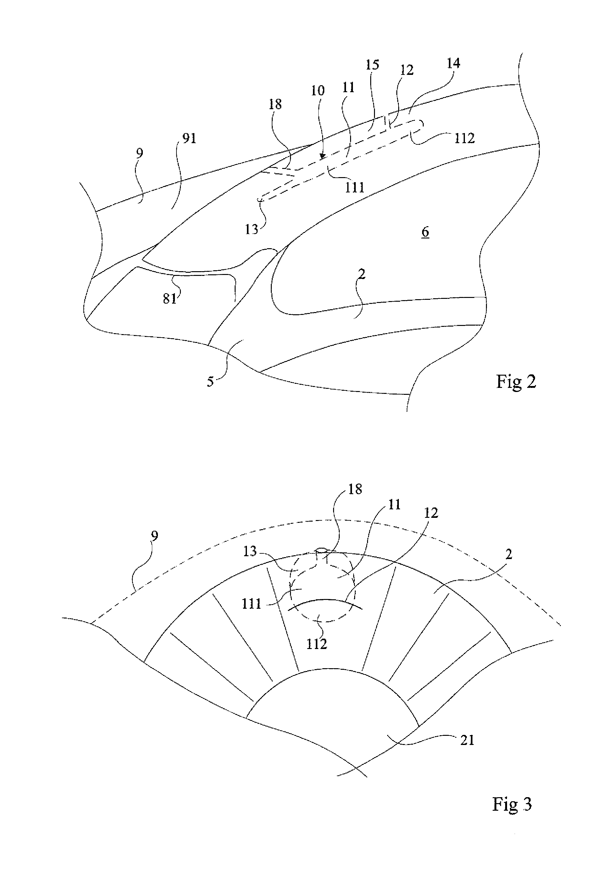
[0048]FIG. 1 is a diagrammatic partial transversal section of an eye which shows, at the back of the cornea 1, iris 2 and lens 3. The external periphery of the iris 2 joins the uvea 5 (the ciliary body) to which is attached the lens 3. The whole is bathed in the aqueous humor 6 (between the cornea and the lens) or the vitreous humor 7 (behind the lens). At the periphery of the cornea is the sclera 8 covered at the exterior by the conjunctiva 9 which forms the white of the eye and which stops at the periphery of the cornea. In the drawing in FIG. 1 the lacrimal canals 81 are shown between the sclera and the cornea. The pupil 21, variable in diameter and formed by the central opening of the iris 2, controls the flow of light penetrating the eye by passing through the cornea.

[0049]The cornea consists of different layers. On the outside is the corneal epithelium 1a which has a thickness of around 50 μm representing approximately 1 / 10th of the total thickness of the cornea. Below it is B...


PUM


Abstract

The invention concerns a system of measuring ocular pressure, consisting of at least one implant (30) including a pressure sensor (33) and an electronic circuit (32), implanted in the cornea of an eye and an antenna (31) connected to the said circuit and implanted in the sub-conjunctival space; and a unit (50) for processing the representative values of the pressure, received by a radio-frequency link from the said electronic circuit (30).

Description

FIELD OF THE INVENTION[0001]The present invention concerns ocular biometry in general and, more particularly, measurement of pressure in the eye.DESCRIPTION OF EARLIER METHODS[0002]Measurement of ocular pressure is used in the diagnosis and investigation of several diseases and to check on the efficiency of certain treatments. Measurement of ocular pressure is used in connection with diseases such as glaucoma. Arteriosclerosis, Horton's disease (temporal arthritis), diabetes, various degenerative family and hereditary pathologies, or those due to age and so on may be the subject of investigation by the analysis of the perfusion output of the head of the optic nerve.[0003]It may be of interest to follow in real time the variations of intra-ocular pressure and the pressure of the central artery of retina for the analysis of the diseases named above.[0004]Up to the present, intra-ocular pressure has been measured by aplanation (tonometry by aplanation) or by air-jet.[0005]These techniq...

Claims


Application Information

Patent Timeline
Patent Type & Authority Applications(United States)
IPC IPC(8): A61B3/16
CPCA61B3/16A61B5/0031A61B5/02438A61B5/02216A61B5/0215A61F9/0017
Inventor TELANDRO, ALAIN
Owner CESACAR PARTICIPACIONS SL
Learn More