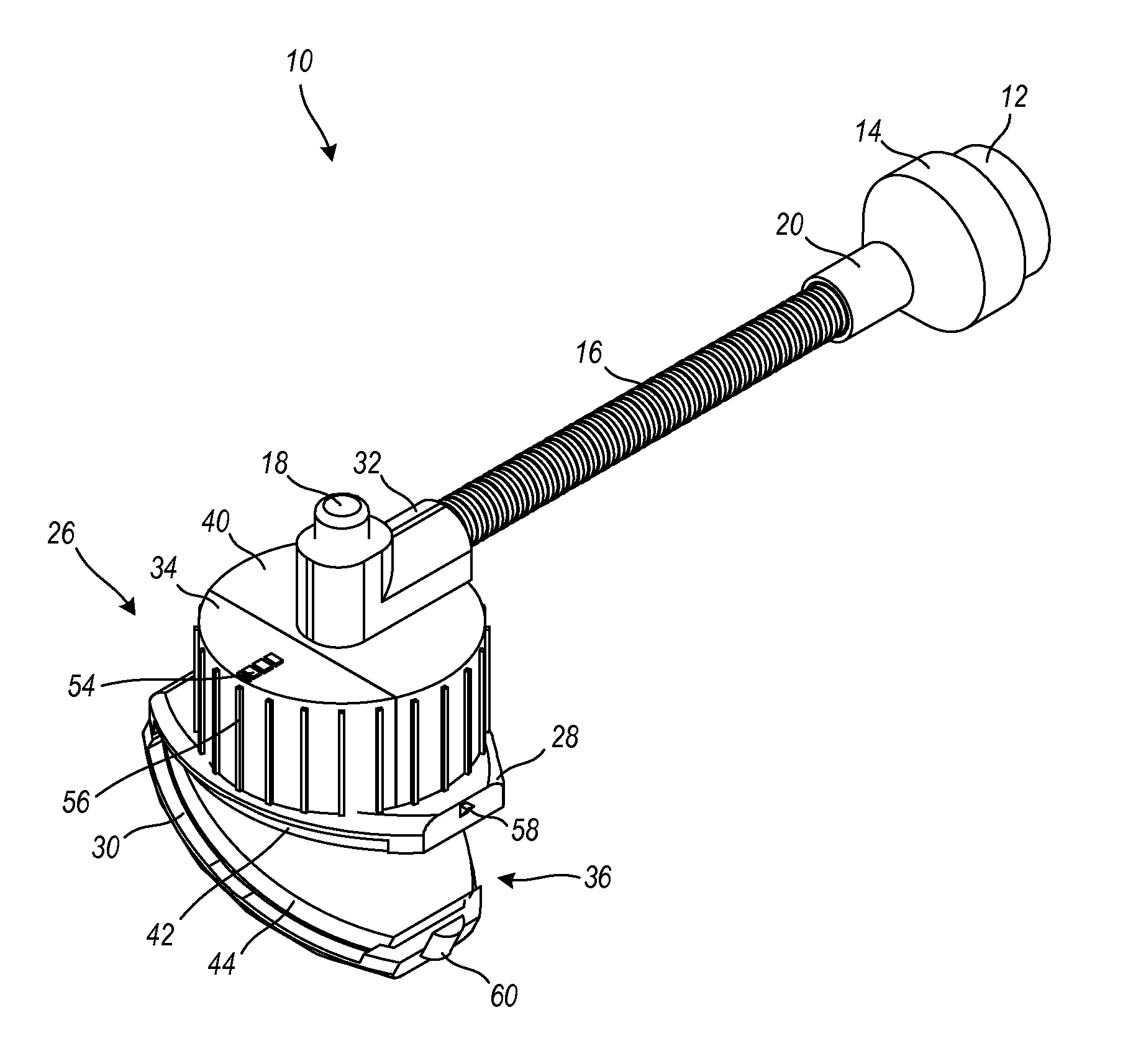

Eyeglass light

a technology for eyeglass frames and lenses, applied in the field of eyeglass light, can solve the problems of no eyeglass frame suitable or adapted for use, and many practical and ergonomic problems, and achieve the effect of quick and easy coupling

Inactive Publication Date: 2012-08-02
GEROLEMOU HELEN KALLOU
View PDF11 Cites 13 Cited by
  • Summary
  • Abstract
  • Description
  • Claims
  • Application Information

AI Technical Summary

Benefits of technology

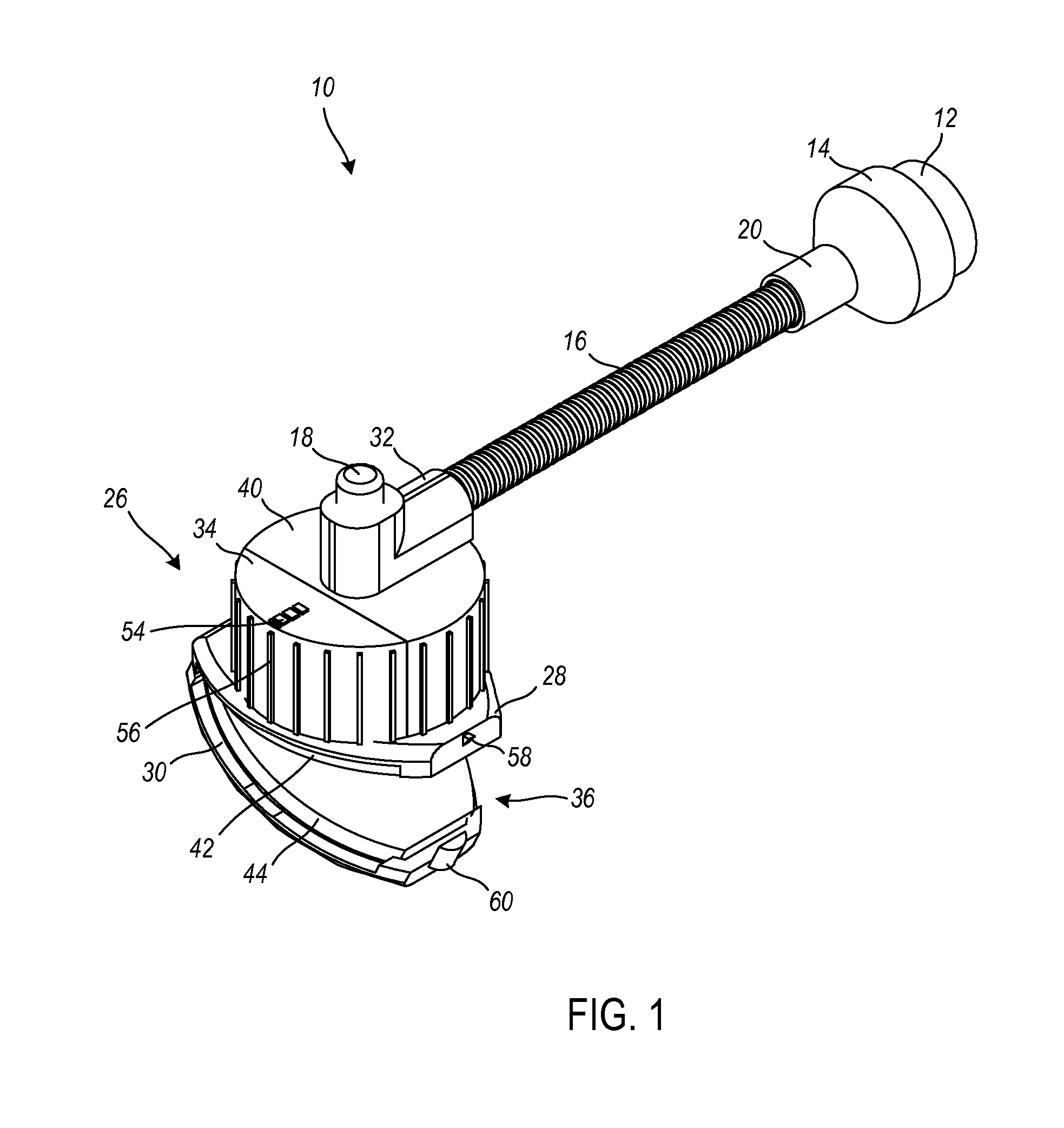
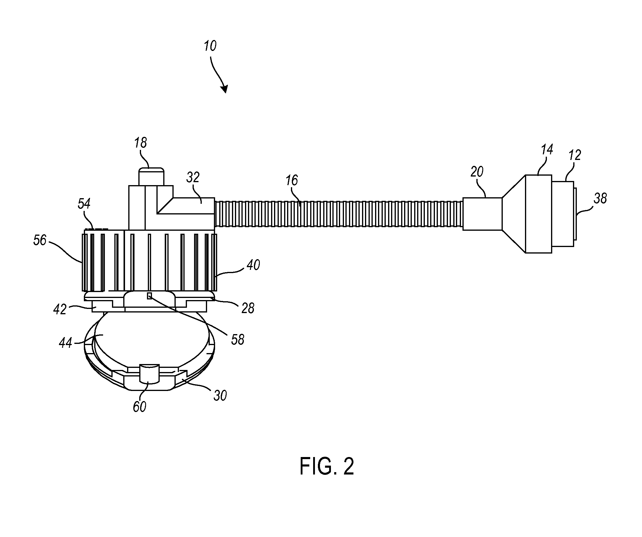
[0017]In embodiments wherein the eyeglass light assembly is adapted to couple to eyeglasses, a preferred point of attachment is the temple area of the eyeglasses. Eyeglasses are known to vary in shape, size, style, and so forth, but most have rims defined to hold a pair of lenses, a bridge adapted to rest upon the nose of the wearer, and temples to secure the rims to the wearer, typically with the temples placed over the tops of the ears to secure the eyeglasses. The eyeglass light assembly is adapted to couple quickly and easily to the temples. Additionally, varied sizes of the eyeglass light assembly can be manufactured to accommodate varied sizes, shapes, and styles of eyeglass temples.
[0020]The eyeglass light assembly includes a stem. The stem is coupled to the light cover. The stem is a flexible tube such as a lightweight metal tube that is bendable by the wearer of the eyeglass light assembly to direct light to a particular area of illumination. The stem, in at least one embodiment, serves as a conduit for a wiring harness, or the like, to transport power to the LED. The stem may include fiber optics. With the stem the eyeglass light assembly is adapted to provide a multiplicity of angle, pivot, and rotation configurations for varied use and adaptation at directing emitted light from an eyeglass frame to a desired area of illumination.

Problems solved by technology

Numerous practical and ergonomic issues exist with these known devices.
There are many shortcomings and deficiencies with known portable illumination devices such that none would be suitable with or adapted for use with an eyeglass frame and the specific needs required for application to an eyeglass frame.

Method used


Image

  • Eyeglass light
  • Eyeglass light
  • Eyeglass light

Examples


Embodiment Construction

[0037]In various exemplary embodiments, the technology described herein provides an eyeglass light assembly. The eyeglass light assembly is an ultra lightweight and configurable eyeglass light adapted to removably and interchangeably attach to an eyeglass frame or, alternatively, to be integrally formed with the eyeglass frame.

[0038]In at least one embodiment, the eyeglass light assembly comprises an overall weight within the range of 0.1 ounces to 0.4 ounces in weight. In at least one embodiment, the eyeglass light assembly comprises an overall weight within the range of 0.1 ounces to 0.9 ounces in weight.

[0039]The eyeglass light assembly is adapted to provide a multiplicity of angle, pivot, and rotation configurations for varied use and adaptation at directing emitted light from an eyeglass frame to a desired area of illumination. The eyeglass light is adapted to pivot and bend in various locations. The eyeglass light provides for hands-free use when mounted. The eyeglass light ca...


PUM


Abstract

An eyeglass light assembly is disclosed. The eyeglass light assembly includes an ultra lightweight and configurable eyeglass light adapted to removably and interchangeably attach to an eyeglass frame or to be integrally formed with the eyeglass frame. The eyeglass light is adapted to provide a multiplicity of angle, pivot, and rotation configurations for varied use and adaptation at directing emitted light from an eyeglass frame. The eyeglass light is adapted to pivot and bend in various locations. The eyeglass light provides for hands-free use when mounted. In one embodiment, the eyeglass light includes and a flexible stem upon which the light is coupled. The stem is further coupled to clip members adapted to couple to one another to secure the assembly to eyeglass frames.

Description

CROSS-REFERENCE TO RELATED APPLICATION(S)[0001]The present non-provisional patent application claims the benefit of priority of U.S. Provisional Patent Application No. 61 / 437,803, which is entitled “EYEGLASS LIGHT”, which was filed on Jan. 31, 2011, and which is incorporated in full by reference herein.FIELD OF THE INVENTION[0002]The technology described herein relates generally to the fields of lighting devices, portable illumination devices, and utility lamps configured to clip onto another object. More specifically, this technology relates to an ultra lightweight and configurable eyeglass light adapted to removably and interchangeably attach to an eyeglass frame. Furthermore, this technology relates to an eyeglass light adapted with a multiplicity of angle, pivot, and rotation configurations for varied use and adaptation at directing emitted light from an eyeglass frame toward a desired area of illumination.BACKGROUND OF THE INVENTION[0003]Portable illumination and lighting devic...

Claims


Application Information

Patent Timeline
Patent Type & Authority Applications(United States)
IPC IPC(8): F21V21/084
CPCF21V21/084F21V21/0885F21V21/145F21L4/00F21Y2101/02G02C11/04F21V21/32F21Y2115/10
Inventor GEROLEMOU, HELEN KALLOU
Owner GEROLEMOU HELEN KALLOU
Learn More