
Video coding device and video coding method

a video coding and video coding technology, applied in the field of video coding devices and video coding methods, can solve the problems of eye fatigue or sickness, cognitive contradiction, and the difficulty of stereoscopically viewing three-dimensional video with compression distortion, and achieve the effect of easy stereoscopic viewing

Inactive Publication Date: 2012-08-02
PANASONIC CORP
View PDF9 Cites 4 Cited by
  • Summary
  • Abstract
  • Description
  • Claims
  • Application Information

AI Technical Summary

Benefits of technology

[0022]The present invention has been made in order to solve the problems above, and an object of the present invention is to provide a video coding device and video coding method in which in coding an input video as a three-dimensional video, a coded video easy to stereoscopically view can be produced.
[0024]Thus, the upper limit value of the quantization width to be used in coding of the two-dimensional video can be set at a different value from the upper limit value of the quantization width to be used in coding of the three-dimensional video. Thereby, the video coding device can set a coding condition according to the viewing characteristics of the two-dimensional video and the three-dimensional video, and can code the two-dimensional video and the three-dimensional video according to the respective video characteristics. Accordingly, the video coding device can produce a coded video easy to stereoscopically view in coding the input video as the three-dimensional video.
[0026]Thus, the video coding device can reduce compression distortion of the video more in coding of the three-dimensional video than in coding of the two-dimensional video. Thereby, for example, even if a viewer does not intentionally change a coding rate when viewing the three-dimensional video, the video coding device can automatically reduce the compression distortion more than in the two-dimensional video in coding of the input video as the three-dimensional video, and produce a coded video easy to stereoscopically view.
[0028]Thus, for example, in the Intra-Picture, the upper limit value of the quantization width can be set higher than that in other type pictures. Thereby, the video coding device can set the coding condition according to the video quality of the picture type, and produce a coded video easier to stereoscopically view in coding of the input video as the three-dimensional video.
[0030]Thus, the video coding device can set the coding condition according to the video characteristics per field, and produce a coded video easier to stereoscopically view in coding of the input video as the three-dimensional video.
[0032]Thus, the video coding device can set the upper limit value of the quantization matrix or the quantization parameter to set the upper limit value of the quantization width. Thereby, the video coding device can produce a coded video easier to stereoscopically view in coding of the input video as the three-dimensional video.

Problems solved by technology

It is known that cognitive contradiction is caused by viewing a three-dimensional video having a great difference in the information perceived by the eyes such as vertical deviation, deviation of inclination, and deviation of the size between the right eye video and the left eye video, causing eye fatigue or sickness (see “A Study on Tolerance for Geometrical Distortions between L / R Images on Shooting 3D-HDTV,” (NHK), IEICE Transactions on Information and Systems Vol.
It is thought that for this reason, cognitive contradiction is caused, and it is more difficult to stereoscopically view the three-dimensional video having compression distortion than in the case of the three-dimensional video having no compression distortion.
For this reason, when the three-dimensional video is recorded, the image quality is more deteriorated, and eye fatigue or sickness is more often caused than in the case of recording in a recording mode at a high recording rate.

Method used


Image

  • Video coding device and video coding method
  • Video coding device and video coding method
  • Video coding device and video coding method

Examples


embodiments

[0042]The present invention can be implemented as a video coding device included in a video capturing apparatus such as a video camera. In the present embodiment, the processing performed by a video camera including the video coding device will be described.

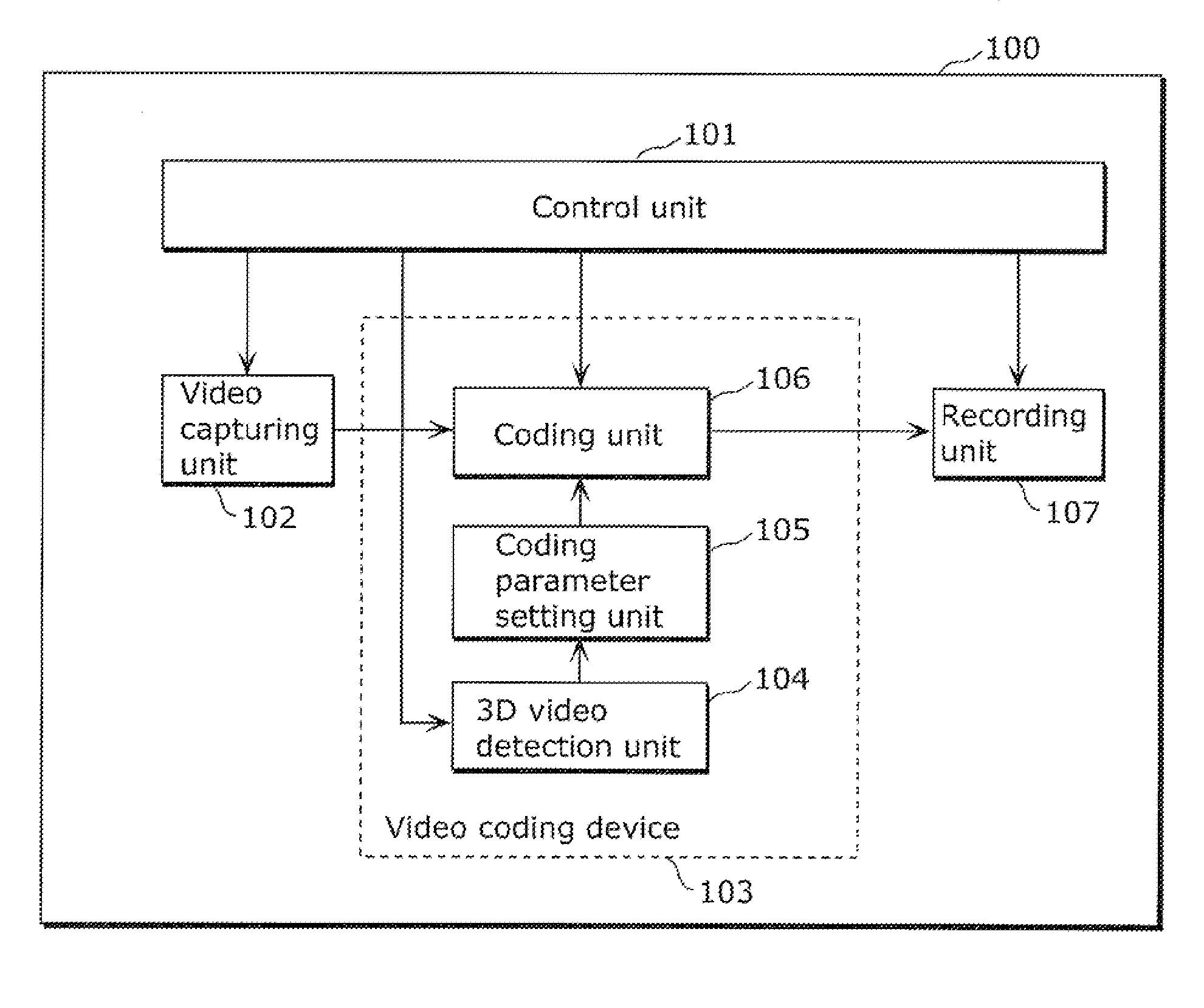
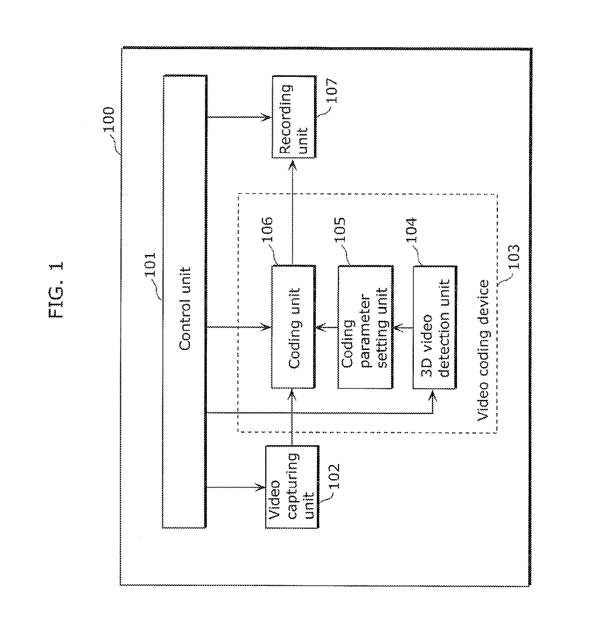
[0043]FIG. 1 is a block diagram showing a configuration of a video camera 100 according to the present embodiment. In the video camera 100 according to the present embodiment, a three-dimensional video or a two-dimensional video is input as an input video, and recorded as a stream coded by the H.264 compression method.

[0044]In the coding by the H.264 compression method, one picture is divided into one or a plurality of slices, and the slice is a processing unit. In the coding by the H.264 compression method according to the present embodiment, one picture is one slice.

[0045]In FIG. 1, the video camera 100 includes a control unit 101, a video capturing unit 102, a video coding device 103, and a recording unit 107. The video coding...

embodiment

Modification of Embodiment

[0098]Next, using FIG. 4, other example of processing performed by the coding parameter setting unit 105 and the coding unit 106 will be described.

[0099]FIG. 4 is a flowchart showing an example of processing performed by the coding parameter setting unit 105 and the coding unit 106 according to a modification of the present embodiment.

[0100]First, based on the detection information input from the three-dimensional video detection unit 104, the coding parameter setting unit 105 determines whether the input video is the two-dimensional video or the three-dimensional video (S401). In the case where the input video is the two-dimensional video, the coding parameter setting unit 105 sets the second upper limit value, and the processing goes to S405. On the other hand, when the input video is the three-dimensional video, the coding parameter setting unit 105 sets the first upper limit value, and the processing goes to S402.

[0101]Next, when the coding parameter se...


PUM


Abstract

A video coding device includes a three-dimensional video detection unit that determines whether an input video is a three-dimensional video or a two-dimensional video, a coding parameter setting unit that sets an upper limit value of a quantization width to be used in coding on the basis of the result of the determination by the three-dimensional video detection unit, and a coding unit that codes the input video at a quantization width not more than the upper limit value set in the coding parameter setting unit, wherein when the three-dimensional video detection unit determines that the input video is the three-dimensional video, the coding parameter setting unit sets the upper limit value of the quantization width for the three-dimensional video at a different value from the upper limit value of the quantization width for two-dimensional video.

Description

CROSS REFERENCE TO RELATED APPLICATIONS[0001]The present application is based on and claims priority of Japanese Patent Application No. 2011-017535 filed on Jan. 31, 2011 and Japanese Patent Application No. 2011-251138 filed on Nov. 16, 2011. The entire disclosures of the above-identified applications, including the specification, drawings and claims are incorporated herein by reference in their entirety.BACKGROUND OF THE INVENTION[0002](1) Field of the Invention[0003]The present invention relates to a video coding device and a video coding method that compression codes a three-dimensional video or a two-dimensional video and records the compression-coded video on a storage medium such as an optical disk, a magnetic disk, or a flash memory.[0004](2) Description of the Related Art[0005]Along with development of a digital video technique, a technique for compression coding digital video data has been developed to treat an increasing amount of data. The development manifests itself in ...

Claims


Application Information

Patent Timeline
Patent Type & Authority Applications(United States)
IPC IPC(8): H04N13/00H04N5/92H04N19/00H04N13/02H04N19/126H04N19/134H04N19/157H04N19/174H04N19/196H04N19/503H04N19/593H04N19/597H04N19/60H04N19/61H04N19/86H04N19/91
CPCH04N13/0048H04N19/124H04N19/597H04N13/161
Inventor MARUYAMA, YUKI
Owner PANASONIC CORP
Learn More