
Identification of fluid flow bottlenecks

a technology of fluid flow and bottlenecks, applied in the direction of relative volume flow measurement, cad techniques, instruments, etc., can solve the problems of excessive energy input, low insight into the reasons for the problem, and the amount of effort required to force, so as to improve the overall fluid flow and flow resistan

Active Publication Date: 2012-08-02
SIEMENS PROD LIFECYCLE MANAGEMENT SOFTWARE INC
View PDF13 Cites 0 Cited by
  • Summary
  • Abstract
  • Description
  • Claims
  • Application Information

AI Technical Summary

Benefits of technology

[0007]The ability to determine where fluid flow bottlenecks exist in a structure enables a designer to make better informed fluid flow design decisions. For example, if a user was considering modifying a structure to make a single reduction in fluid flow resistance, relatively higher fluid flow bottleneck characteristic values would indicate where best to make the modifications so as to maximize the reduction in pressure drop within the structure. Similarly, the ability to determine where there are shortcut opportunities to insert new fluid flow paths in a structure enable a user to make better informed fluidic design decisions. For example, if a user was considering where to add a single new flow path to a structure, relatively higher fluid flow shortcut characteristic values would indicate where best to place the new channel or opening in the structure so as to shortcut the fluid flow to other areas, thus reducing the pressure drops within the structure.

Problems solved by technology

Such visualizations will enable observations of what the flow is doing but little insight into the reasons why.
In terms of fluid flow, the amount of effort required to force fluid to move through a system at a desired speed is a function of the flow restrictive nature of that system.
System with excessive pressure drop require excessive energy input to drive the fluid at the required flow rates, via use of fans, pumps etc.
While these tools have been useful in revealing fluid flow in various devices, they typically provide no guidance as to how a device can be modified to change its heat flow.
As a result, many product designers may overlook more efficient device modifications for improving fluid flow, and instead employ less effective, more bulky, and / or more expensive techniques to reduce temperature in a device.

Method used


Image

  • Identification of fluid flow bottlenecks
  • Identification of fluid flow bottlenecks
  • Identification of fluid flow bottlenecks

Examples


Embodiment Construction

Exemplary Operating Environment

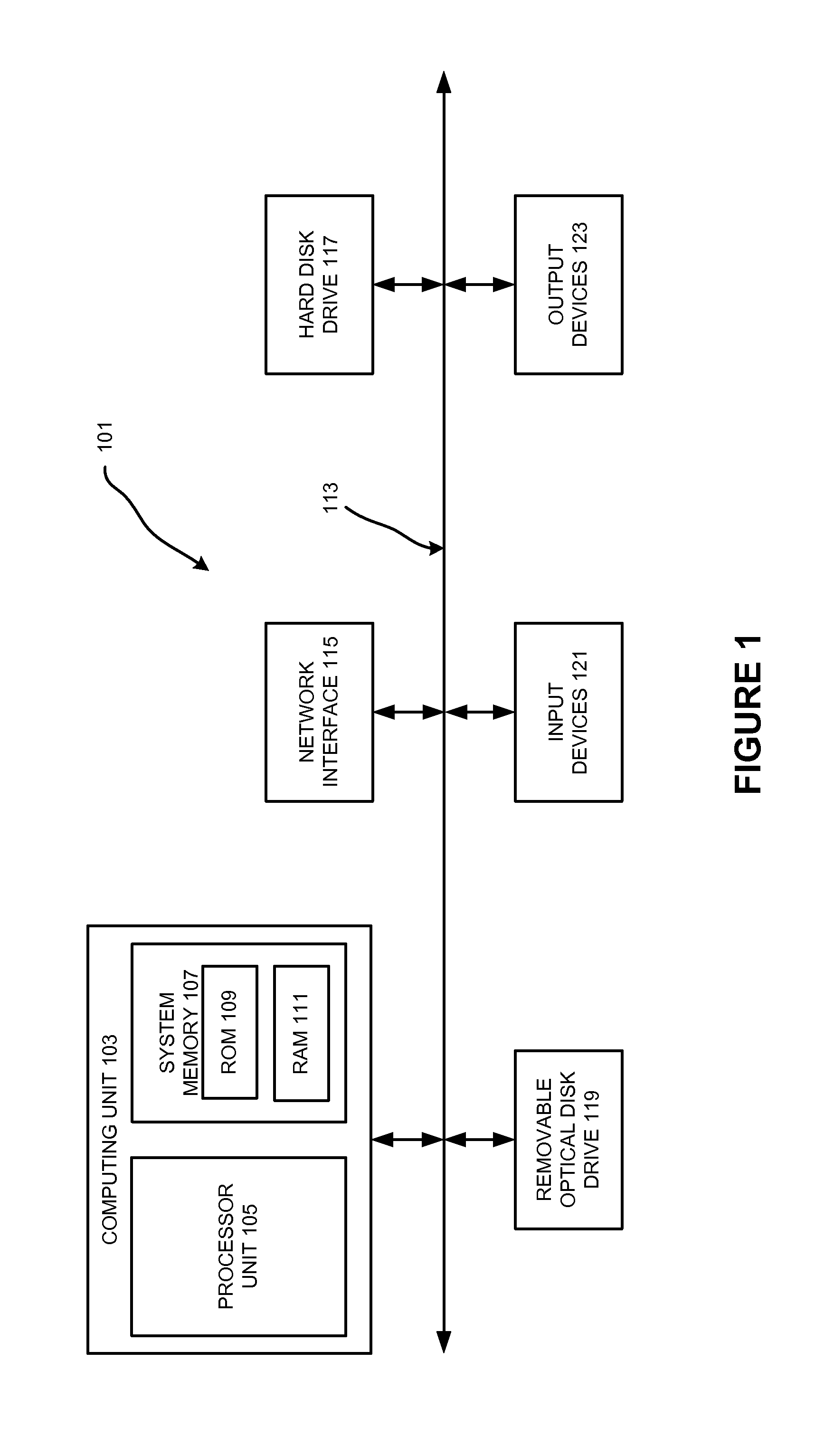
[0016]Various examples of the invention may be implemented through the execution of software instructions by a computing device, such as a programmable computer. Accordingly, FIG. 1 shows an illustrative example of a computing device 101. As seen in this figure, the computing device 101 includes a computing unit 103 with a processing unit 105 and a system memory 107. The processing unit 105 may be any type of programmable electronic device for executing software instructions, but will conventionally be a microprocessor. The system memory 107 may include both a read-only memory (ROM) 109 and a random access memory (RAM) 111. As will be appreciated by those of ordinary skill in the art, both the read-only memory (ROM) 109 and the random access memory (RAM) 111 may store software instructions for execution by the processing unit 105.

[0017]The processing unit 105 and the system memory 107 are connected, either directly or indirectly, through a bus 113 or a...


PUM


Abstract

Techniques for determining one or more fluid flow characteristic values of a structure are disclosed. A fluid flow vector and a pressure gradient vector for a portion of the structure are determined, and a dot / cross product of the fluid flow vector with the pressure gradient vector is obtained to provide a fluid flow characteristic value. The fluid flow characteristic value can be used for modifying the structure to improve fluid flow through the structure.

Description

FIELD OF THE INVENTION[0001]The present invention is directed to the analysis and visualization of fluid flow through various structures. Various aspects of the invention may be particularly useful for identifying regions in a structure that restrict the fluid flow to improve the structure design.BACKGROUND OF THE INVENTION[0002]Computational Fluid Dynamics (CFD) is a mathematical method of solving the governing equations of fluid flow on a computer and visualizing the resulting distribution of flow properties such as pressure, speed and temperature on a three-dimensional mesh. Such visualizations will enable observations of what the flow is doing but little insight into the reasons why. In terms of fluid flow, the amount of effort required to force fluid to move through a system at a desired speed is a function of the flow restrictive nature of that system.[0003]The desire to minimize or control pressure differences in a fluid flow system is a reoccurring need when it comes to the ...

Claims


Application Information

Patent Timeline
Patent Type & Authority Applications(United States)
IPC IPC(8): G01F5/00
CPCG06F17/5018G01F9/00G06F2217/16G06F30/23G06F2111/10
Inventor BORNOFF, ROBINBLACKMORE, BYRONPARRY, JOHN
Owner SIEMENS PROD LIFECYCLE MANAGEMENT SOFTWARE INC
Learn More