Mobile communication system, base station, network device, and control method and program thereof
- Summary
- Abstract
- Description
- Claims
- Application Information
AI Technical Summary
Benefits of technology
Problems solved by technology
Method used
Image
Examples
first exemplary embodiment
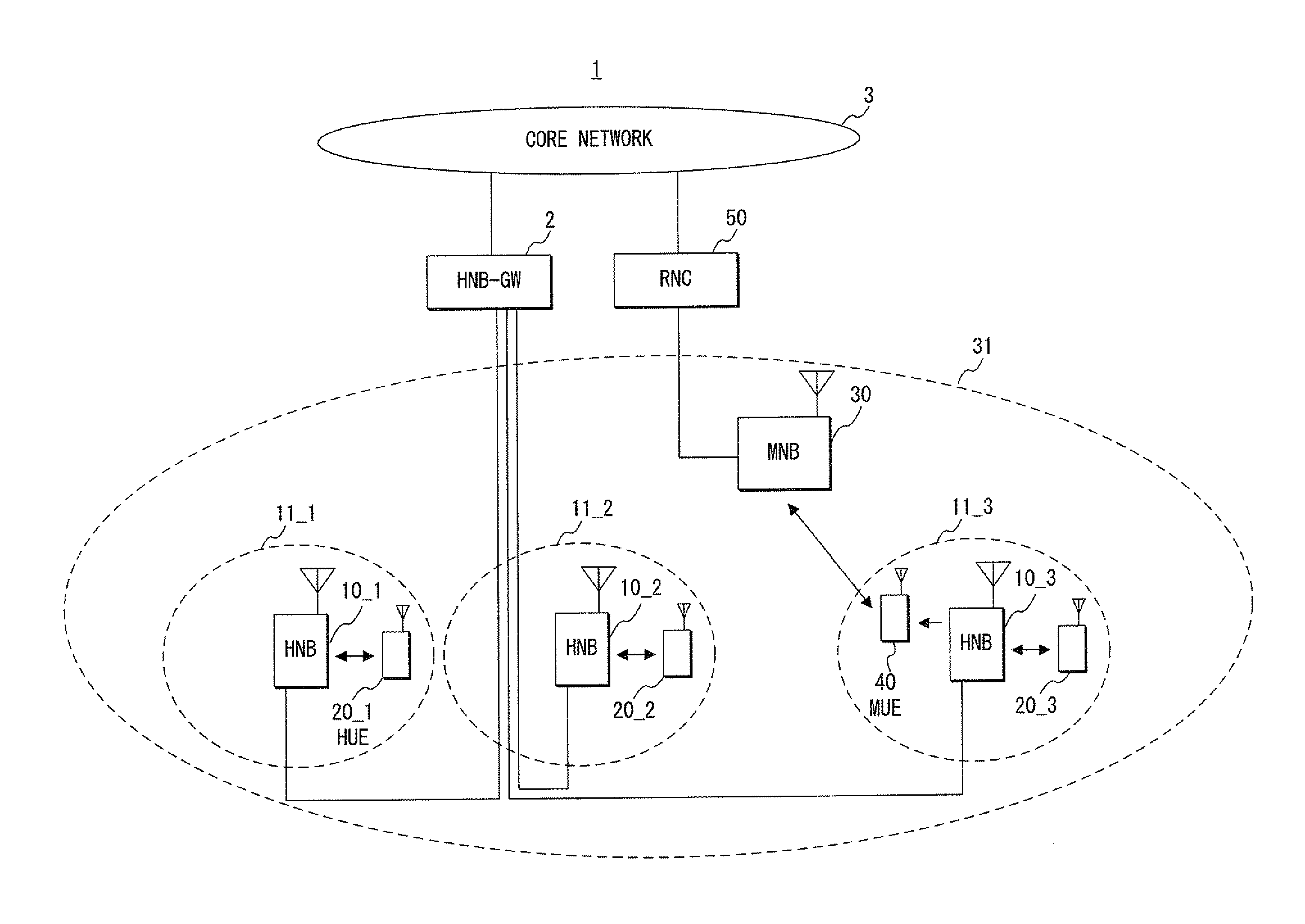
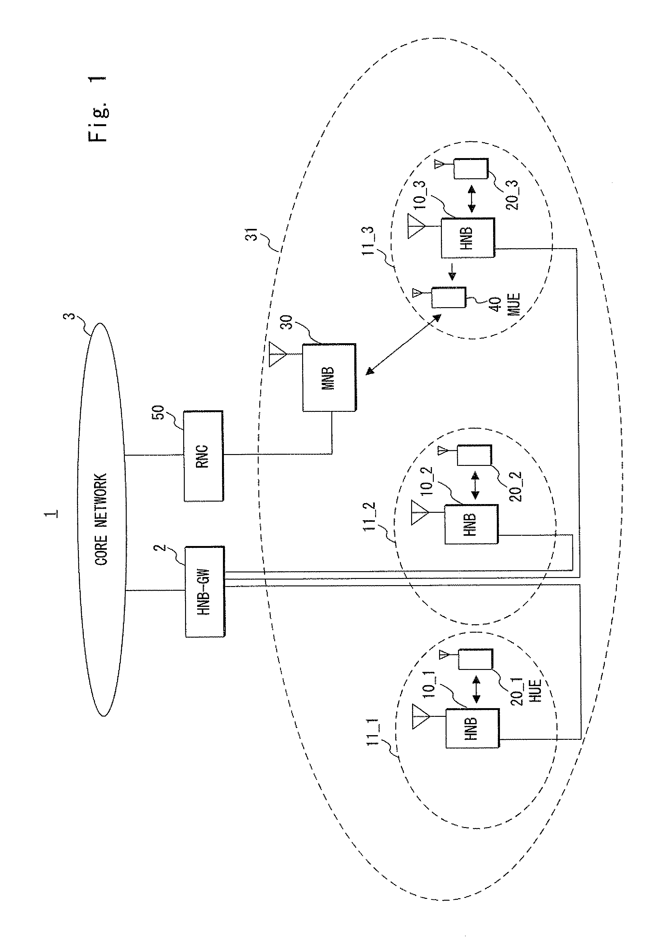
[0039]FIG. 1 shows an example of a schematic structure of a mobile communication system 1 according to this exemplary embodiment. Note that, in this exemplary embodiment and the second and third exemplary embodiments described later, a case where communication compliant with W-CDMA (Wideband Code Division Multiple Access) is conducted is described as an example.
[0040]Three home base stations (HNB) 10_1 to 10_3, for example, that constitute the mobile communication system 1 form home cells 11_1 to 11_3, respectively, and thereby conduct radio communication with pre-registered home user equipments (HUE: Home UE) 20_1 to 20_3. Note that, in the following explanation, the HNBs 10_1 to 10_3 are collectively denoted by the symbol 10, the HUEs 20_1 to 20_3 are collectively denoted by the symbol 20, and the home cells 11_1 to 11_3 are collectively denoted by the symbol 11 in some cases. Further, the number of HUEs connected to each home cell may be more than one.
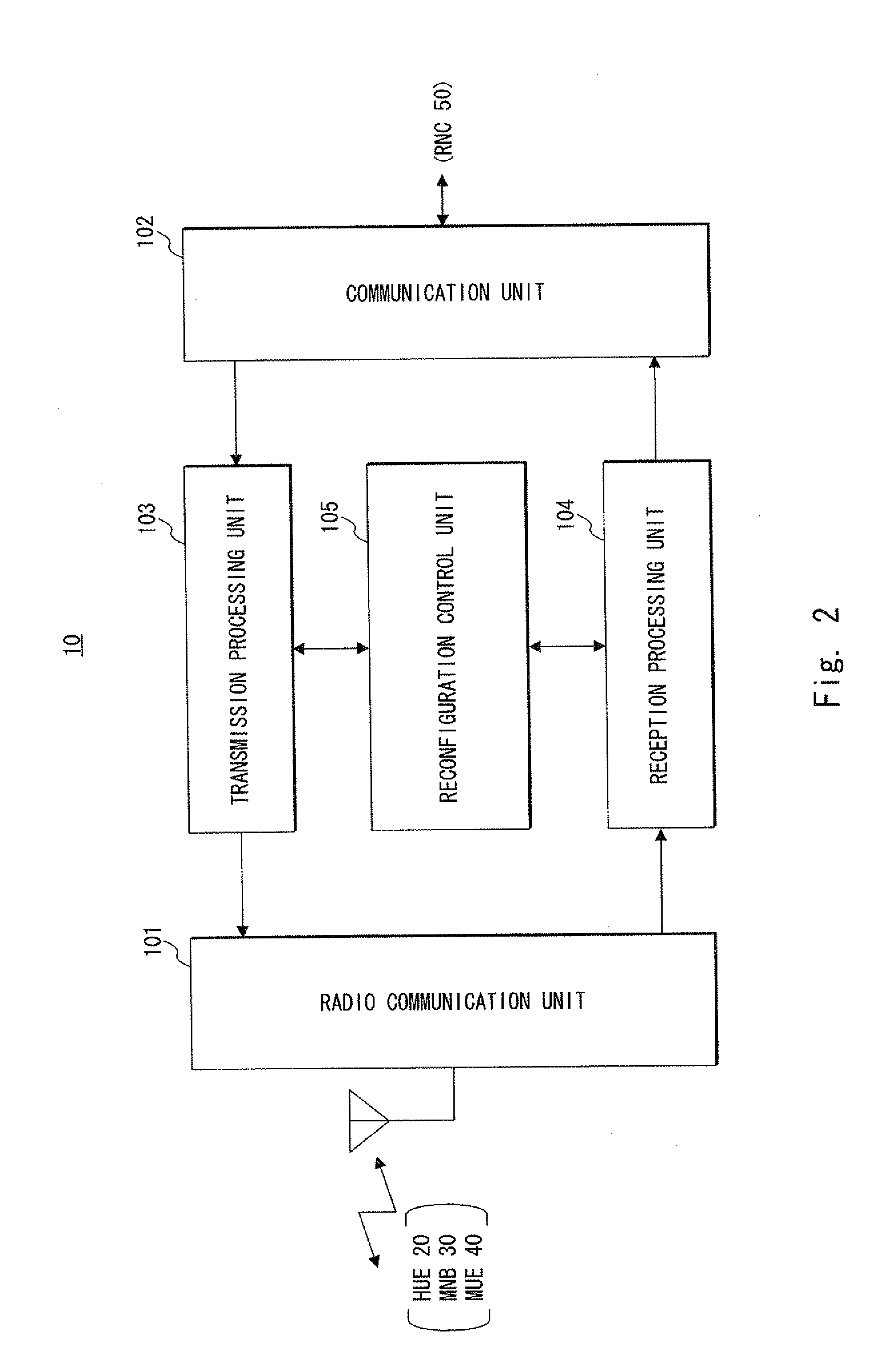
[0041]The HNB 10 is connecte...
second exemplary embodiment
[0072]A mobile communication system according to this exemplary embodiment has the same structure as the mobile communication system 1 described above in the first exemplary embodiment.
[0073]In the operation, as shown in FIG. 9, the RNC 50 executes processing shown at Step S108 in place of Steps S104 and S105 shown in FIG. 5. To be specific, the RNC 50 transmits reconfiguration requests to the HNBs 10_1 to 10_3 installed in the macro cell 31 to which the MUE 40 belongs, without selecting candidates for the HNB to which a reconfiguration request is to be transmitted. Note that the RNC 50 may transmit a reconfiguration request to some of the HNBs installed in the macro cell 31.
[0074]Each of the HNBs 10_1 to 10_3 determines whether or not to perform reconfiguration on each of the home cells 11_1 and 11_3 based on uplink interference to its own HNB (Step S109). To be specific, as shown in FIG. 10, the HNB 10 executes processing shown at Step S405 in addition to Steps S5401 to S404 shown...
third exemplary embodiment
[0080]A mobile communication system according to this exemplary embodiment has the same structure as the mobile communication system 1 described earlier in the first exemplary embodiment.
[0081]In the operation, as shown in FIG. 11, the RNC 50 selects the HNBs 10_1 and 10_3 as candidates for the HNB to which a reconfiguration request is to be transmitted and transmits reconfiguration requests to the HNBs 10_1 and 10_3 as at Steps S104 and S105 shown in FIG. 5.
[0082]Each of the HNBs 10_1 and 10_3 determines whether or not to perform reconfiguration on the home cells 11_1 and 11_3 based on uplink interference to its own HNB as at Step S109 shown in FIG. 9. As a result, only the HNB 10_3, which is the actual source of interference, performs the reconfiguration of the home cell.
[0083]As described above, according to this exemplary embodiment, the home cell serving as the source of interference to the MUE can be selected accurately just like the second exemplary embodiment described above...
PUM
 Abstract
Description
Claims
Application Information
 - R&D
- Intellectual Property
- Life Sciences
- Materials
- Tech Scout
- Unparalleled Data Quality
- Higher Quality Content
- 60% Fewer Hallucinations
Browse by: Latest US Patents, China's latest patents, Technical Efficacy Thesaurus, Application Domain, Technology Topic, Popular Technical Reports.
© 2025 PatSnap. All rights reserved.Legal|Privacy policy|Modern Slavery Act Transparency Statement|Sitemap|About US| Contact US: help@patsnap.com


