
System and method of calibrating a system

a technology of system and calibration method, applied in the field of system and method of calibration system, to achieve the effect of improving the speed and and improving the accuracy of the detection of indicators

Active Publication Date: 2012-07-26
TIMETRONICS
View PDF4 Cites 11 Cited by
  • Summary
  • Abstract
  • Description
  • Claims
  • Application Information

AI Technical Summary

Benefits of technology

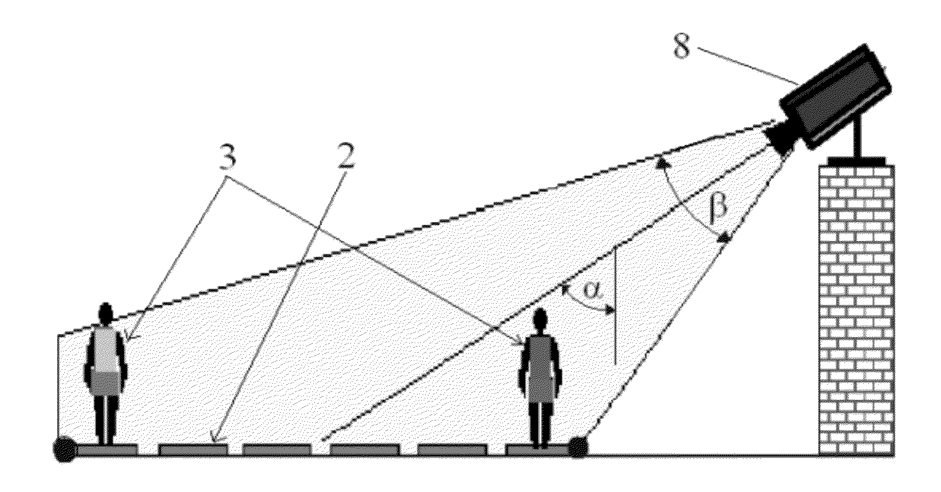
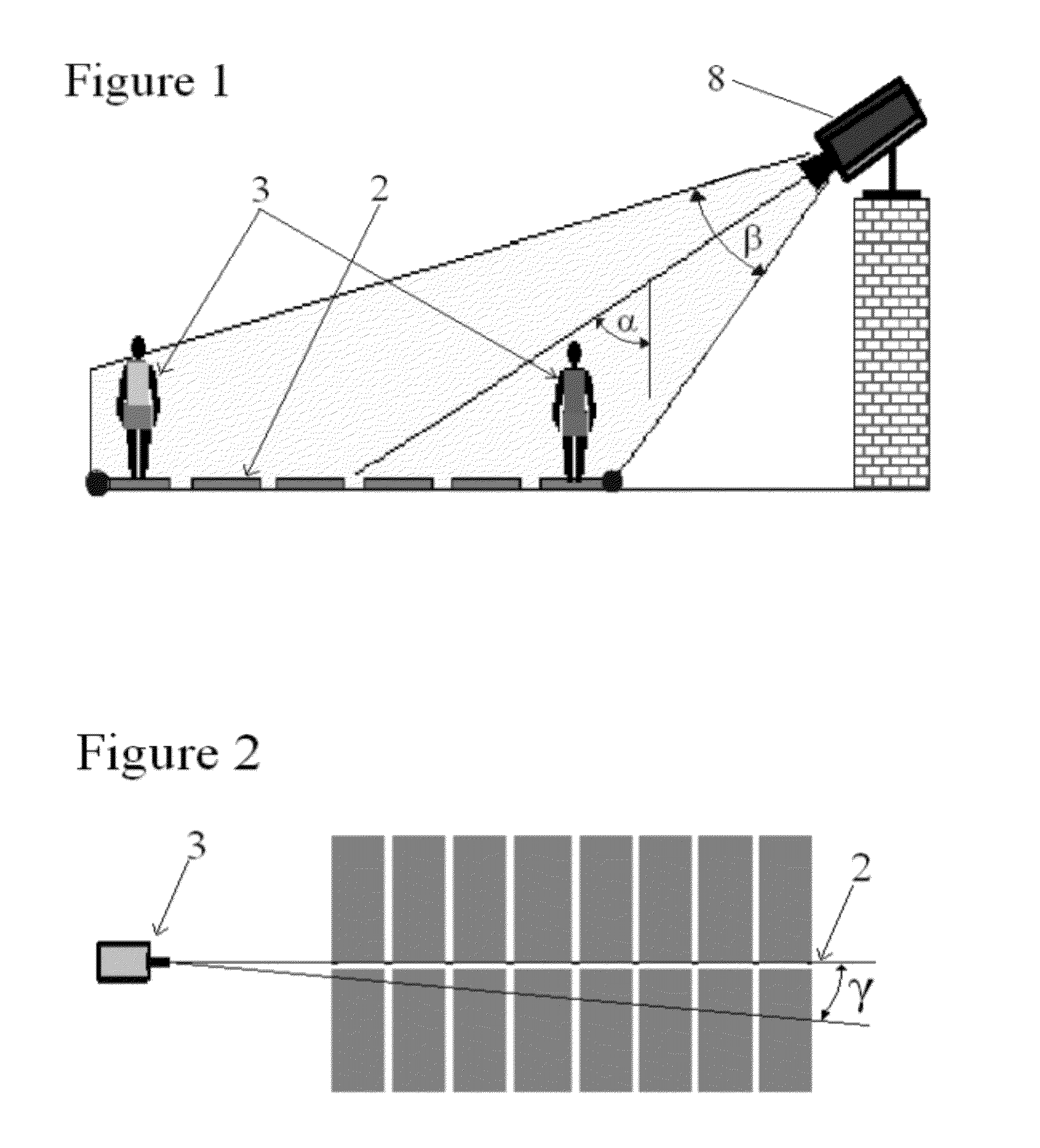
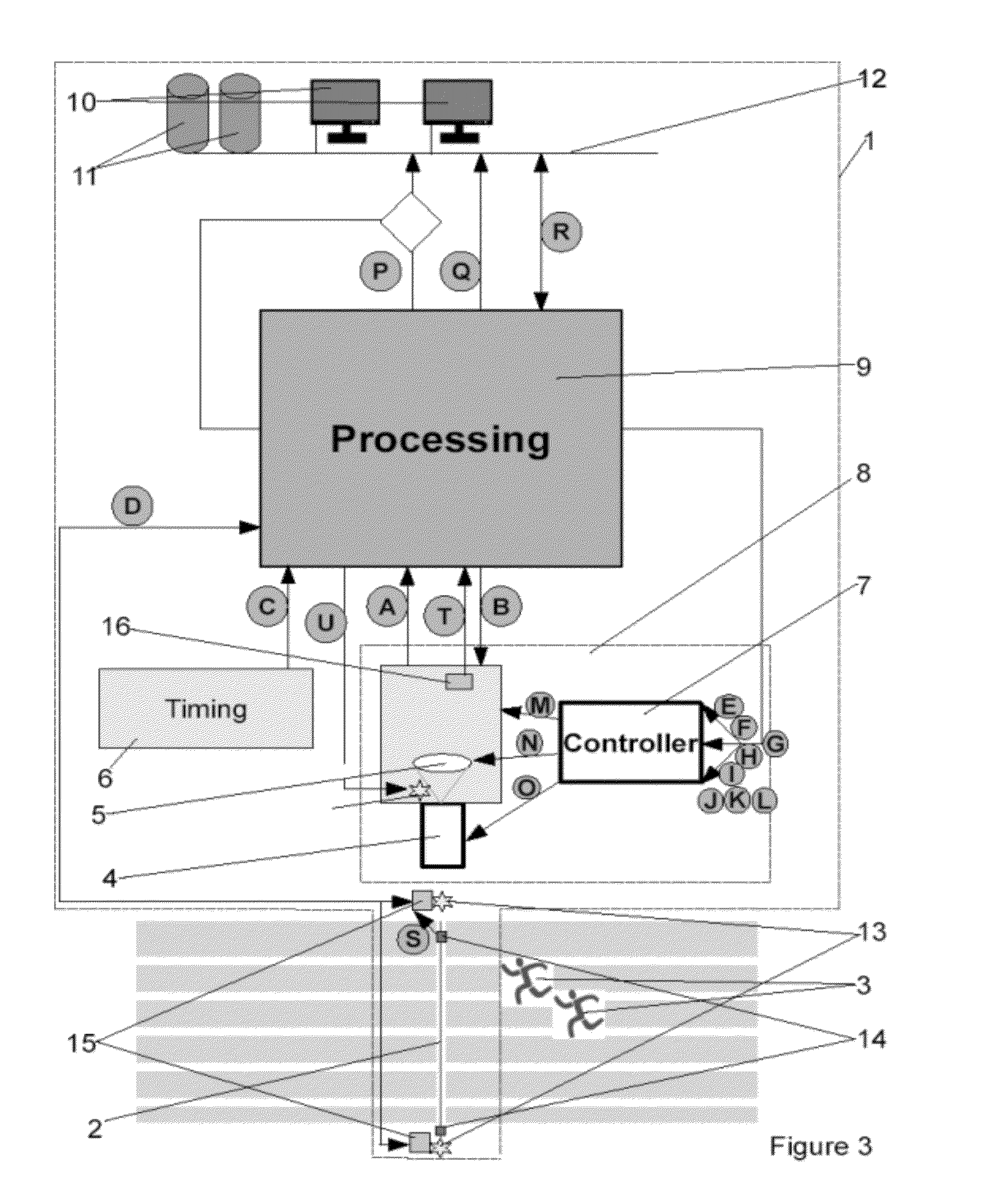
[0046]Preferably, use is made of more than one separately located indicator, wherein the first and second indicator are located at different distances from the camera. The provision of a first and a second optical indicator enables the automatic calibration of both the horizontal alignment and the vertical alignment of the camera. The first and second indicator are preferably located on opposite ends or extensions of the line of passage. Such positioning allows continued use of the indicators during operation of the system without hindrance to any participant. Such continued use enables the execution of a recalibration of the system. An alternative positioning of the indicators is a location above each other. In an advantageous positioning, a third indicator is added right above the first one, so that the three indicators are positioned in a vertical plane to the ground level and passing through the line of passage. These locations effectively enable calibration of the camera perfectly horizontally level (e.g. as obtained by a spirit level) and in extension of the line of passage. This is for instance carried out by adjusting the viewed image such that all said three indicators are visible in the same sensor column of the sensor.
[0049]It is observed for clarity that the light emitted by the active optical indicator may include visible light, infrared and ultraviolet radiation. Visible light is most recognizable. It is thus most suitable for use by less experienced users. Infrared and ultraviolet radiation have the advantage of not disturbing any visual registration for television, in a photograph or by individual spectators watching the sports event. That may be particularly relevant in professional sports events.
[0050]In an advantageous embodiment, the one or more active indicators are light emitting devices such as LED transmitters. A LED transmitter comprising one or more light emitting diodes is a type of point-like indicators; i.e. their size is almost negligible in comparison to traditional lamps. This makes that the first height of the indicators can be defined very precisely. Moreover, the use of LED transmitters typically increases speed and accuracy of the detection of the indicators. Additionally, particularly with the use of LED transmitters, it allows more complex coding.
[0055]Preferably, the system is provided with a calibration mode and an operation mode. The image in said calibration mode then represents a wider view than in the operation mode. Particularly, the camera suitably registers image signals in the form of matrices, when operating in the calibration mode. Therewith a two-dimensional image of the finish line and its surroundings (before and after the finish line when viewed along the lane) is given. In the operation mode, the camera suitably registers images in the form of pixel lines, thus generating an image of the finish line over time. The advantage of the latter is that the frequency is increased. The number of pixel lines per image registered in the operation mode tends to depend on the sports type. In many cases, it will be in the range of 1 to 10, but for certain sports, it may be above 100.

Problems solved by technology

In most cases the precision of this time recording is 1*10-3 s, where the resolution could be easily 1*10-6 s. This high frequency that is clearly above the standard 50 or 60 Hz for displaying on a screen, is a major problem in the field.
All of these prior art system suffer from the problem of calibrating the system in order to align the camera perfect with the passage line.

Method used


Image

  • System and method of calibrating a system
  • System and method of calibrating a system
  • System and method of calibrating a system

Examples


Embodiment Construction

[0063]The present invention will be described with respect to particular embodiments and with reference to certain drawings but the invention is not limited thereto but only by the claims. The drawings described are only schematic and are non-limiting. In the drawings, the size of some of the elements may be exaggerated and not drawn on scale for illustrative purposes. Where the term “comprising” is used in the present description and claims, it does not exclude other elements or steps. Where an indefinite or definite article is used when referring to a singular noun e.g. “a” or “an”, “the”, this includes a plural of that noun unless something else is specifically stated.

[0064]The term “comprising”, used in the claims, should not be interpreted as being restricted to the means listed thereafter; it does not exclude other elements or steps. Thus, the scope of the expression “a device comprising means A and B” should not be limited to devices consisting only of components A and B. It ...


PUM


Abstract

The system measures time of at least one object on the basis of passing a finish line and includes a camera with a photosensitive sensor and a lens for registering an image of the line. The image is sent to a processor for processing. Timing means deliver a timing signal to the processor. The system is at least partially automatically aligned. It thereto comprises a first active optical indicator that is located at a predefined location with reference to the line of passage, which indicator is detected as part of the image registered by the camera so as to obtain detection data. The system further includes a camera adjustment arrangement for adjustment of the orientation of a center axis of the camera, said adjustment being specified by the processor on the basis of the detection data.

Description

[0001]The invention relates to a system and method for the measurement of a time period, especially in sports time measurement, wherein said time period is measured on the basis of passing a line of passage of at least one object, such as a finish line of a race, said line of passage being drawn on a ground level.[0002]The invention also relates to a method of calibrating such a system, to a method of recalibration and use of the calibrated system for measurement of a time period.BACKGROUND[0003]Systems for the measurement of a time period are well known and widely applied in sports time measurement. One of key elements is a camera, also referred to as a photofinish camera. This camera is special, for several reasons. First of all, It has to record very high speed images (“1-D” line or “2-D” image), currently in most systems from 100 to 2000 images per second. In addition thereto, each image has to be exactly time-tagged, with the race-time or day-time or other time-reference. In mo...

Claims


Application Information

Patent Timeline
IPC IPC(8): H04N17/00
CPCG07C1/24
Inventor VANUYTVEN, EDDY
Owner TIMETRONICS
Learn More