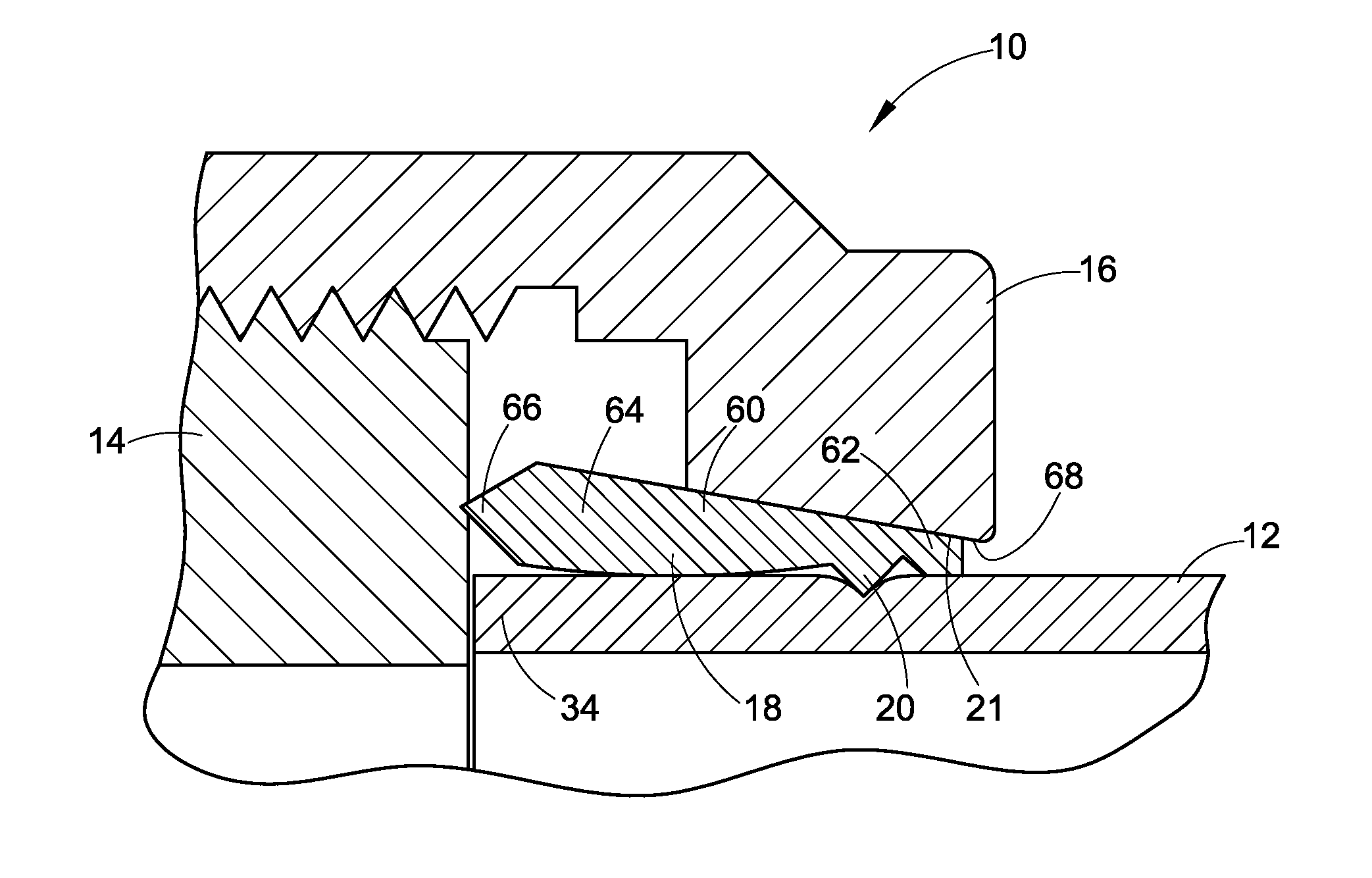
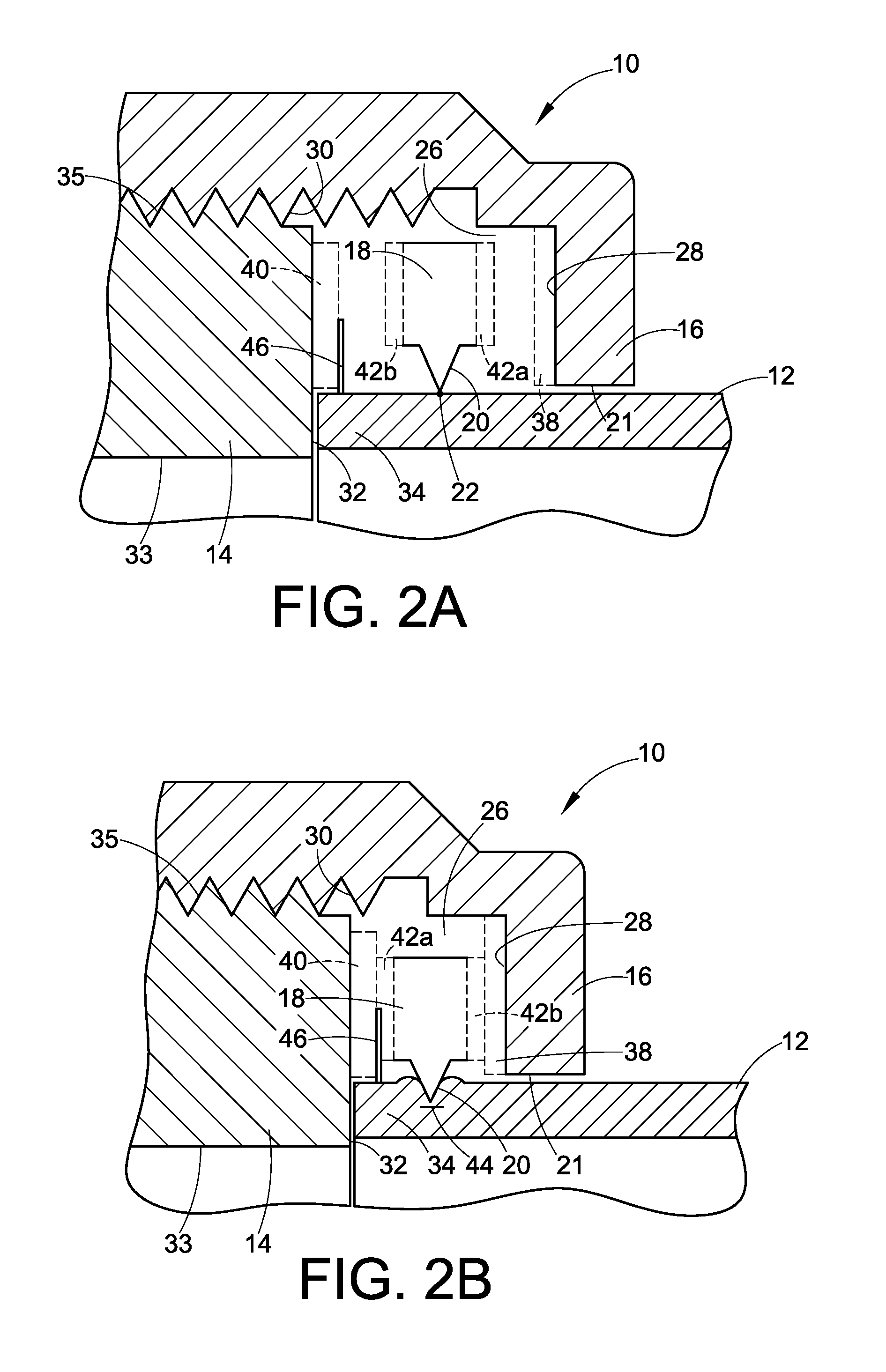
[0004]According to one aspect of the present application, a fitting is provided that limits plastic deformation of a tube to which the fitting is assembled. As one example, plastic deformation may be limited to a narrow ring of engagement between the tube and a tube indenting edge on a tube gripping member. In one embodiment, this narrow ring of engagement may be achieved by providing the tube indenting edge of the tube gripping member with a sharp radius, which may focus the indenting or cutting engagement between the tube gripping member and the tube to a narrow ring. A narrow ring of engagement may additionally or alternatively be achieved by hardening at least the tube indenting edge of the tube gripping member, such as with a low temperature carburization process, to minimize deformation of the tube indenting edge during fitting assembly and, as a result, to minimize the region of contact between the tube indenting edge and the tube. Since the region of engagement between the tube gripping member and the tube is reduced, the amount of force required to be applied by the fitting member to plastically deform the tube material is likewise reduced. This may be of particular benefit in use with thin walled tubing, which may be able to support the significantly reduced force that is applied to the tube along a narrow ring of engagement with a tube gripping member. As a result, when such a fitting is used with thin walled tube, the thin walled tube may not need to be flared and placed over a fitting member.
[0005]According to another aspect of the present application, a fitting may additionally or alternatively be configured to reinforce or back up an end of the tubing, thereby providing support for the forces applied by the fitting to the tubing, such as the force that is applied by, for example, a tube gripping member, to plastically deform the tube material and form a seal. In one embodiment, an annular groove or recess may be provided in a fitting body end face to receive and reinforce the tube end. In another embodiment, a groove, recess, or other reinforcement structure may be provided in a fitting component assembled with a fitting body, such as a gland or gasket. This aspect may also be of particular benefit in use with thin walled tubing, as support or reinforcement for the end of the tubing may prevent or minimize unwanted deformation of the tubing during pull-up, such as deformation away from a highly localized region of engagement between a fitting member and the thin walled tube. This aspect may also eliminate the need for flaring of the thin walled tube, as the fitting is adapted to support or reinforce an unaltered tube end.
[0006]According to yet another aspect of the present invention, a fitting may be configured such that the a tube may be assembled with or separated from a fitting body without substantial axial movement of the tube with respect to the fitting body, thereby allowing separation or assembly with substantially zero clearance between the fitting body and the tube. In one such embodiment, the tube end abuts an end face of the fitting body. As such, the tube would not need to be axially withdrawn from an end of the fitting body during disassembly. In another embodiment, a sealing structure, for example on a tube gripping member or on another fitting component, seals against an end face of the fitting body. As such, the sealing structure would not need to be axially withdrawn from an end of the fitting body during disassembly. Additionally, when used with thin walled tubing, the elimination of a flared end on the tubing, as described above, may also facilitate assembly and disassembly of the fitting with substantially zero clearance.
[0007]Other aspects of the present application may also be provided, alone or in combination, with the above aspects, with various exemplary fittings, to facilitate ease of assembly, sealing capability, adaptability for use with various types of tubing and in various types of systems and applications, as well as other benefits. These other aspects include, but are not limited to: providing a fitting component with a damping portion that engages the tube to limit vibration at the end of the tube assembled with the fitting; providing a hinging mechanism in a tube gripping member to pivot the gripping member into engagement with a tube when a fitting is tightened; providing a flexing mechanism in a tube gripping member to flex the gripping member into engagement with a tube when a fitting is tightened; providing an intermediary sealing member between a tube gripping member and a fitting body; providing a colleting member to transfer a gripping force from a fitting component, such as a fitting body or nut, to a tube gripping member; providing a tube alignment structure, for example, on a fitting body or a sealing member, to axially align a tube within a fitting; providing a separate cam member in a fitting to direct a tube gripping member into engagement with a tube when the fitting is tightened; providing a fitting component, such as a tube gripping member, in a shape memory alloy, such that a gripping force is applied when the component returns to its remembered shape; applying a substance, such as a lubricant, to one or more fitting components to enhance fitting performance; and providing a clamping structure for clamping a tube against a reinforcement structure of a fitting to seal against the tube when the fitting is assembled.


