
Trusted Partner Medical Records System and Method

Inactive Publication Date: 2012-07-12
EPIC SYST CORP (US)
View PDF2 Cites 16 Cited by
  • Summary
  • Abstract
  • Description
  • Claims
  • Application Information

AI Technical Summary

Benefits of technology

[0025]In this environment where a small group of entities routinely provide services to the same patients, it has been recognized that the problems described above that are associated with separate entities maintaining separate EMR systems can be overcome by establishing a special trusted partners relationship between entities wherein physicians working through one of the entities automatically obtain patient data initially generated by other entities in the partnership. Thus, for instance, when a physician initially requests a patient chart from one trusted partner subset entity, the query results in an automatic collecting of patient chart data from all other entities in the trusted partnership so that the physician need not manually request the patient charts from the other trusted subset entities.
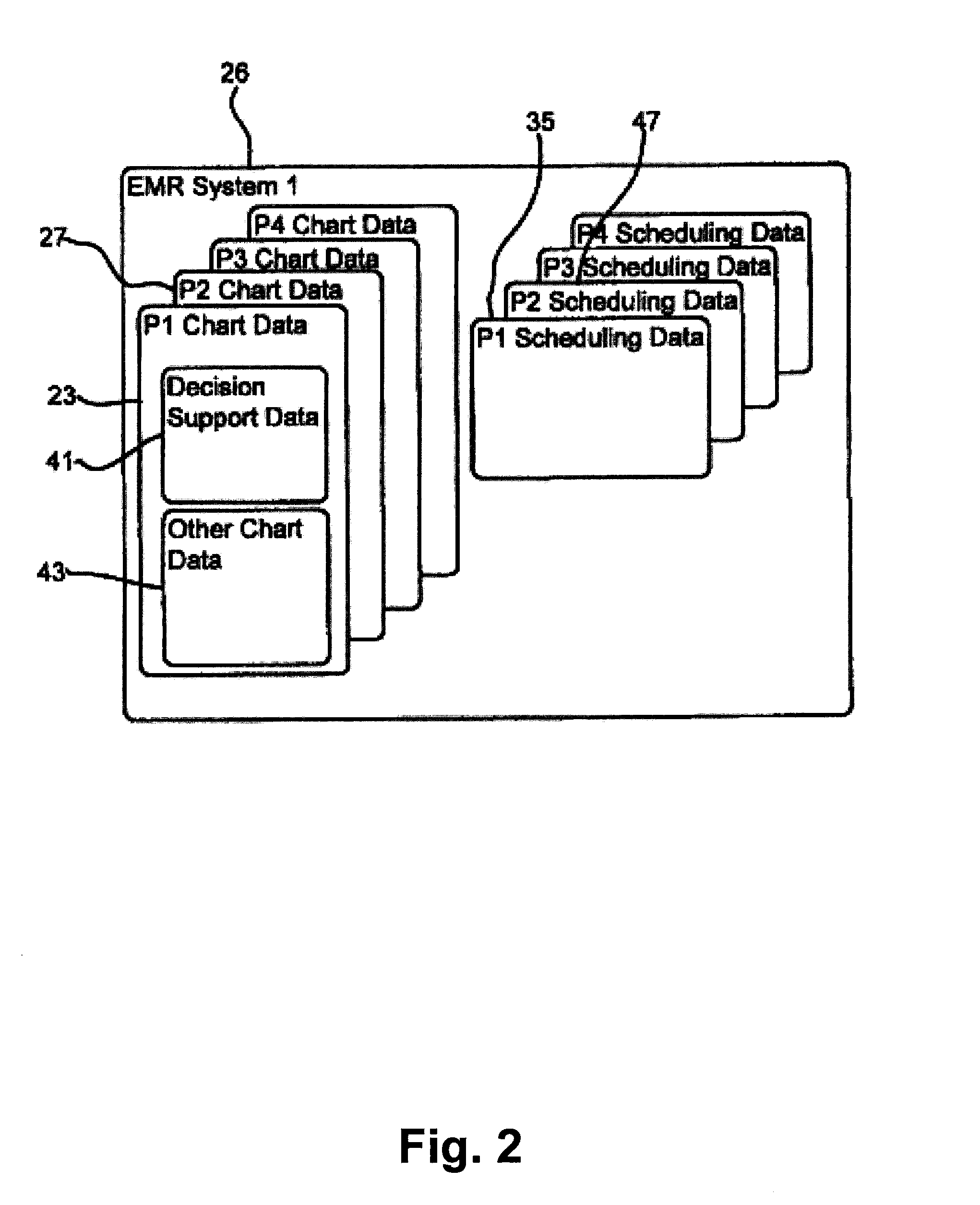
[0026]In addition, in at least some cases, after the trusted partnership is established between a set of entities, when changes are made to data in an EMR system associated with one of the trusted subset entities, the changes are used to automatically update the other trusted subset entity EMR systems. Here, in at least some cases, patient chart data will include first and second different subsets and the automatic synchronization is only performed for the first data subset. In some cases the first data subset includes decision support data which is routinely used by physicians to make medical decisions for patients while the second data set includes other less routinely consulted data. What constitutes “decision support” data may be different in different systems. This automatic synchronization increases the speed with which a physician can access patient chart data that is initially generated by a plurality of entities that each maintain separate EMR systems in two ways. First, the physician need not query each separate EMR system for patient data. Second, because decision support data is automatically synchronized, access to the most important patient chart data from all of the trusted subset entities can be accessed at any one of the trusted subset entities without further access to the entities that initially generated the data.

Problems solved by technology

One major shortcoming of separate EMR systems is that the separate systems result in barriers between physicians and patient data required to facilitate optimal patient services.
Thus, where a physician accesses only a single EMR system (i.e., the EMR system maintained by a facility / entity that the physician works at) to obtain medication information for a patient, often times the physician will only have access to incomplete medication information that specifies a subset of the medications that a patient is currently taking or has taken The physician does not have access to medication information in any other EMR systems and therefore may have incomplete information.
Without knowing schedule information from multiple EMR systems, it is essentially impossible for a scheduling physician to optimally schedule future activities for a patient.
Multiple authorizations and requests are burdensome to both patients and physicians.
While this solution facilitates the option to update an EMR system with current information, the manual acceptance requirement is burdensome.
Third, in many cases, when patient charts or schedule data is obtained from first and second different EMR systems, the charts / data are presented to a physician as separate information sets which makes it cumbersome to locate, view and comprehend all relevant information.
In fact, in the present example, when first and second charts from first and second separate EMR systems are presented, they are typically presented in separate data screens or views requiring a physician to switch back and forth among the shots to view the entire allergies list, which is time-consuming and potentially confusing as a physician attempts to reconcile differences between the two lists.
The problem of separate chart views is exacerbated when a physician accesses patient data from more than two separate EMR systems as movement and reconciliation is required among several different screens.
Similar problems occur when scheduling information is accessed from separate EMR systems as the different schedules are not integrated and instead are presented as multiple different views.
Fourth, push and pull chart sharing processes between separate entities that call for transmission of large and detailed patient charts can require several minutes to complete.
Unfortunately, chart sharing and schedule sharing processes are commonplace and will likely increase in the future and execution time delay will become more annoying to system users.
Fifth, patient authorization for entities to share data are typically for relatively short periods of time (e.g., one month or one visit) and / or usually authorize only limited sharing of data.
For this reason, often multiple patient authorizations are required for sharing among two entities which is annoying to many patients and which can slow down the process of patient care.
One problem with the centralized exchange model is that it requires a large and often times expensive centralized infrastructure including servers, systems, administrators, etc.
Another problem with the centralized exchange model is that centralized exchange data is often times not well maintained since physicians are not directly using these systems.
In many other cases, upon affiliation, each separate institution already has a legacy EMR system and moving to a single EMR system is considered cost prohibitive.
Thus, accessing all patient charts from all affiliated institutions is time consuming and the end result, separate charts, is cumbersome to comprehend and use.

Method used


Image

  • Trusted Partner Medical Records System and Method
  • Trusted Partner Medical Records System and Method
  • Trusted Partner Medical Records System and Method

Examples


Embodiment Construction

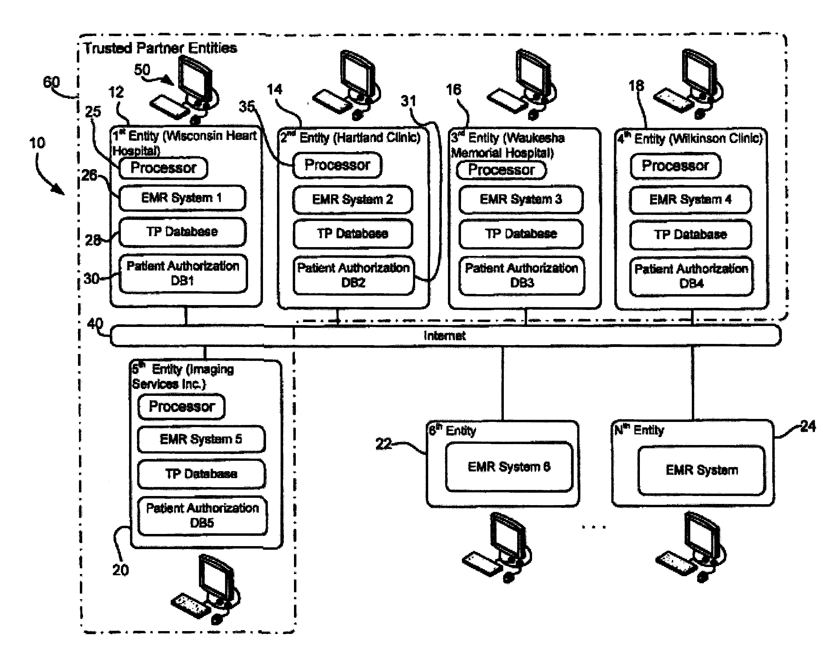
[0044]Referring now to the drawings wherein like reference numerals correspond to similar elements through the several views and, more specifically, referring to FIG. 1, the present invention will be described in the context of exemplary information and communication system 10 that includes, among other things, a plurality of different entities 12, 14, 16, 18, 20, 22 and 24, that are each linked to a communication network such as the internet 40 that enables communication between the separate entities. Each of the exemplary entities 12-24 represents a separate medical facility. For example, the first entity 12 represents Wisconsin Heart Hospital and the second through fifth entities, 14, 16, 18 and 20 represent Hartland Clinic, Waukesha Memorial Hospital, Wilkinson Clinic and Imaging Services Inc., respectively. While each of the exemplary entities only represents a single medical facility, it should be appreciated that some entities may represent more than one facility where the en...


PUM


Abstract

A method and system for sharing patient medical records among a plurality of separate entities wherein each of the entities maintains a separate electronic medical records (EMR) system, the method comprising the steps of receiving a first data request associated with a first patient via a first entity where the first entity is a requesting, automatically identifying the EMR systems associated with a trusted subset of entities that maintain at least a subset of data associated with the first patient, using the subsets of data from the identified EMR systems to update patient data maintained by the requesting entity wherein the patient data includes patient medical chart data and using the updated patient data maintained by the requesting entity to generate and present a patient medical chart via a display.

Description

CROSS-REFERENCE TO RELATED APPLICATIONS[0001]Not applicable.STATEMENT REGARDING FEDERALLY SPONSORED RESEARCH OR DEVELOPMENT[0002]Not applicable.BACKGROUND OF THE INVENTION[0003]1. Field of the Invention[0004]The present invention relates to electronic medical records systems and more specifically to a system wherein a plurality of separate entities maintain separate electronic medical records systems, wherein the entities can establish trusted relationships wherein trusted subset entities automatically obtain each others patient medical data as patients move among the trusted subset entities as if the data is owned and managed by each of the trusted subset entities and, in at least some cases, so that updates to data at one of the entities are automatically used to modify the data at the other of the trusted subset entities.[0005]2. Description of the Related Art[0006]Hereinafter various concepts will be described in the context of the medical industry. Nevertheless, it should be ap...

Claims


Application Information

Patent Timeline
IPC IPC(8): G06Q50/24G16H10/60G16H40/67
CPCG06Q50/24G06Q10/10G16H40/67G16H10/60
Inventor FUHRMANN, DAVID E.CASSEL, DAVID ANDREWDEVAULT, PETER
Owner EPIC SYST CORP (US)
Learn More