
Apparatus and method for treating a regurgitant heart valve

Active Publication Date: 2012-07-12
THE CLEVELAND CLINIC FOUND
View PDF55 Cites 23 Cited by
  • Summary
  • Abstract
  • Description
  • Claims
  • Application Information

AI Technical Summary

Benefits of technology

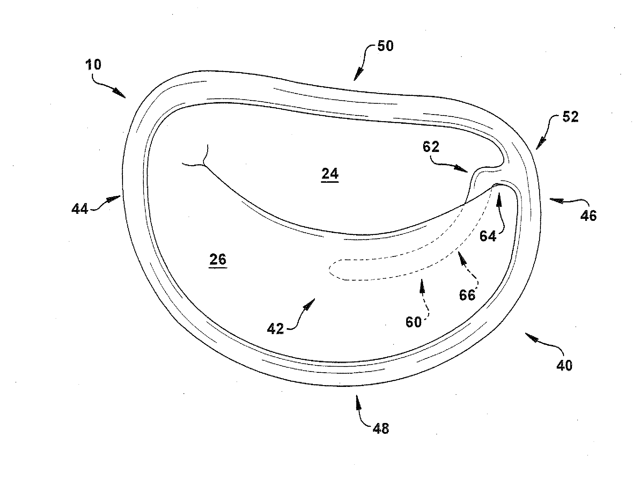
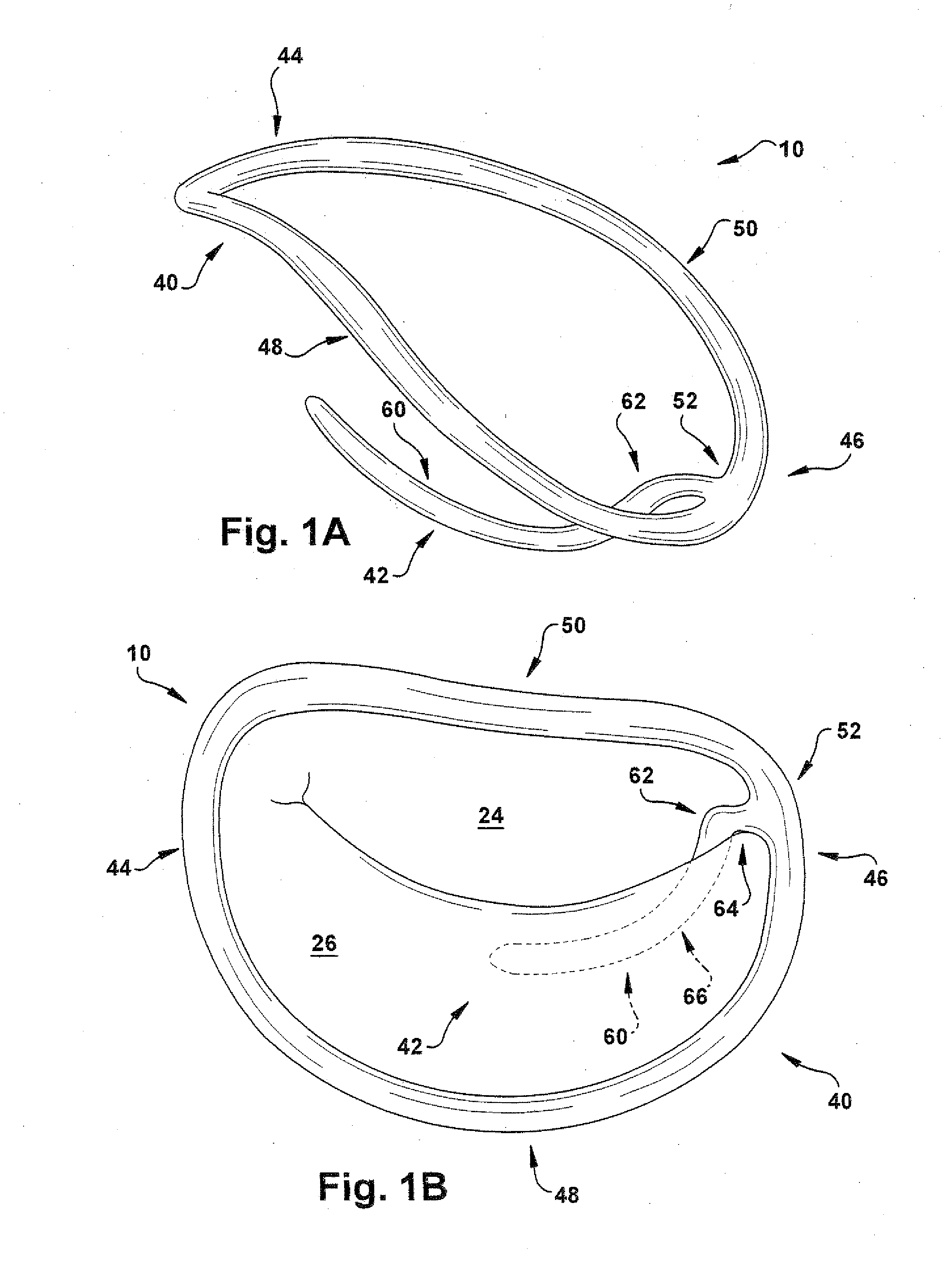
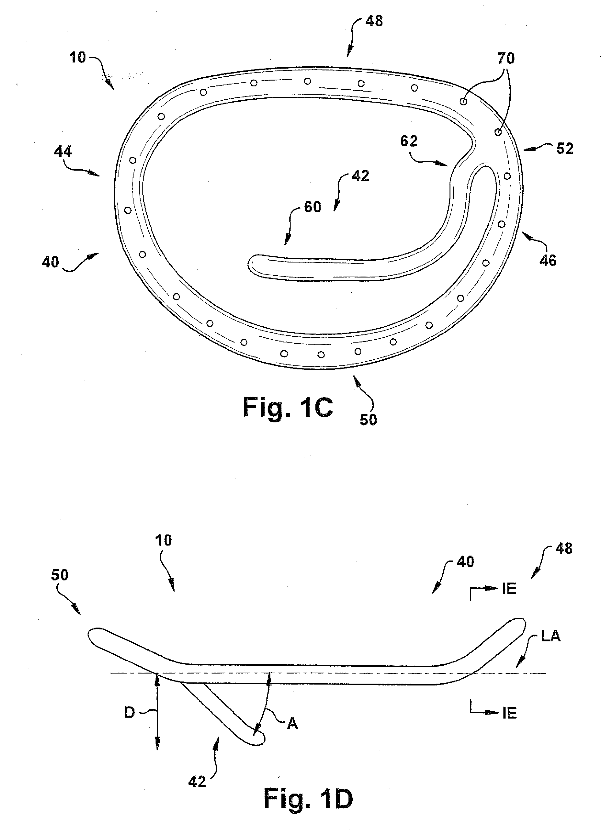
[0009]According to another aspect of the present invention, a method is provided for treating regurgitation of blood flow through a diseased heart valve. The diseased heart valve includes an annulus, an anterior valve leaflet and a posterior valve leaflet. One step of the method includes providing an apparatus comprising a substantially annular support member and at least one infra-annular support member that is securely connected thereto. The substantially annular support member includes at least a first intermediate portion, a second intermediate portion, and a posterior end portion extending between the first and second intermediate portions. Next, the substantially annular support member is attached to the annulus of the diseased heart valve so that the at least one infra-annular support member extends below at least one of the posterior and anterior valve leaflets and across or behind at least one subvalvular structure to prevent or substantially reduce regurgitation of blood flow through the diseased heart valve.

Problems solved by technology

When the high pressure produced by contraction of the left ventricle pushes the valve leaflets too much, the leaflets become everted and prolapse results.
Although complete correction of mitral regurgitation has been surgically demonstrated, an important recurrence of mitral regurgitation after annuloplasty valve repair is common (25%) because the left ventricle continues to dilate or remodel, thereby causing further tethering of the mitral leaflets.

Method used


Image

  • Apparatus and method for treating a regurgitant heart valve
  • Apparatus and method for treating a regurgitant heart valve
  • Apparatus and method for treating a regurgitant heart valve

Examples


Embodiment Construction

[0073]The present invention relates generally to apparatus and methods for treating dysfunctional heart valves, and more particularly to apparatus and related methods that provide sub-valvular leaflet support, as well as sub-valvular apparatus support to passively assist in preventing or mitigating heart valve regurgitation. The present invention generally provides an annuloplasty ring system having an infra-annular, free-edge leaflet and subvalvular apparatus supporting mechanism that prevents valve leaflet tethering and regurgitation during systole. Advantageously, the present invention provides simultaneous annular and sub-annular levels of cardiac remodeling of a cardiac valve (mitral and tricuspid) to correct and normalize the level and angle of leaflet coaptation, prevent valve leaflet tethering, and resolve recurrent valve regurgitation over time. Consequently, the present invention provides treatment for not only regurgitation (e.g., functional mitral regurgitation), but als...


PUM


Abstract

An apparatus is provided for treating regurgitation of blood flow through a diseased heart valve. The diseased heart valve includes an annulus, anterior and posterior valve leaflets, and a subvalvular apparatus. The apparatus includes a substantially annular support member and at least one infra-annular support member securely connected thereto. The substantially annular support member has at least a first intermediate portion, a second intermediate portion, and a posterior end portion extending between the first and second intermediate portions. The posterior end portion is dimensioned for attachment to a posterior portion of the annulus of the diseased heart valve. The at least one infra-annular support member is securely connected to the substantially annular support member at a first location. The at least one infra-annular support member is dimensioned to extend below at least one of the posterior and anterior valve leaflets and across or behind at least one subvalvular structure.

Description

RELATED APPLICATIONS [0001]This application is a continuation-in-part of U.S. patent application Ser. No. 12 / 274,087, filed Nov. 19, 2008, which claims the benefit of U.S. Provisional Patent Application Ser. No. 60 / 988,825, filed Nov. 19, 2007 (now Expired). This application also claims the benefit of U.S. Provisional Patent Application Ser. No. 61 / 429,543, filed Jan. 4, 2011. All of the above-identified applications, from which priority is claimed, are incorporated herein by reference in their entireties for all purposes.TECHNICAL FIELD [0002]The present invention relates generally to apparatus and methods for treating dysfunctional heart valves, and more particularly to apparatus and related methods that provide sub-valvular leaflet support, as well as sub-valvular apparatus support to passively assist in preventing or mitigating heart valve regurgitation.BACKGROUND OF THE INVENTION[0003]The opening and closing of heart valves occur primarily as a result of pressure differences. F...

Claims


Application Information

Patent Timeline
IPC IPC(8): A61F2/24
CPCA61F2/2445A61F2/2448A61F2/2496A61F2/2466A61F2/2454F04C2270/0421
Inventor NAVIA, JOSE L.
Owner THE CLEVELAND CLINIC FOUND
Learn More