
Power supply controller

a power supply controller and controller technology, applied in pulse technique, emergency protective arrangements responsive to undesired changes, instruments, etc., can solve the problems of large thermal capacity of wires and switch elements, and achieve the effect of reducing the number of counters

Active Publication Date: 2012-07-12
AUTONETWORKS TECH LTD +2
View PDF10 Cites 21 Cited by
  • Summary
  • Abstract
  • Description
  • Claims
  • Application Information

AI Technical Summary

Benefits of technology

[0018]The present invention enables reducing the number of the counters which are used to protect the switch element.

Problems solved by technology

In such a power supply controller, if an overcurrent flows, the switch element may burn out or a wire (power supply path) may smoke in some cases.
However, the wire has a large thermal capacity as compared to the switch element.

Method used


Image

  • Power supply controller
  • Power supply controller
  • Power supply controller

Examples


Embodiment Construction

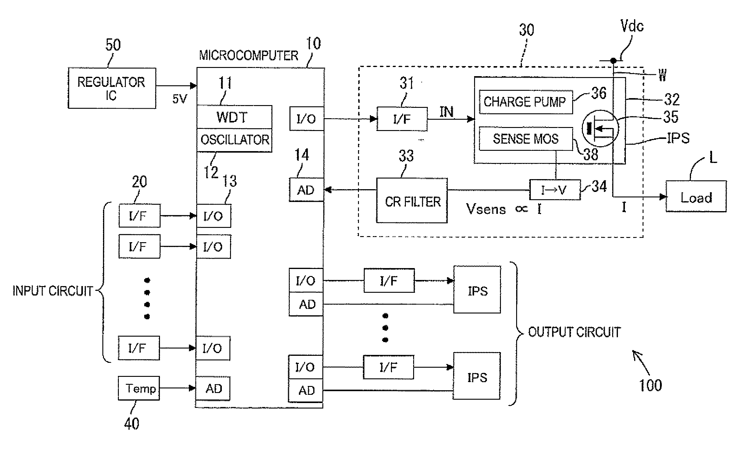
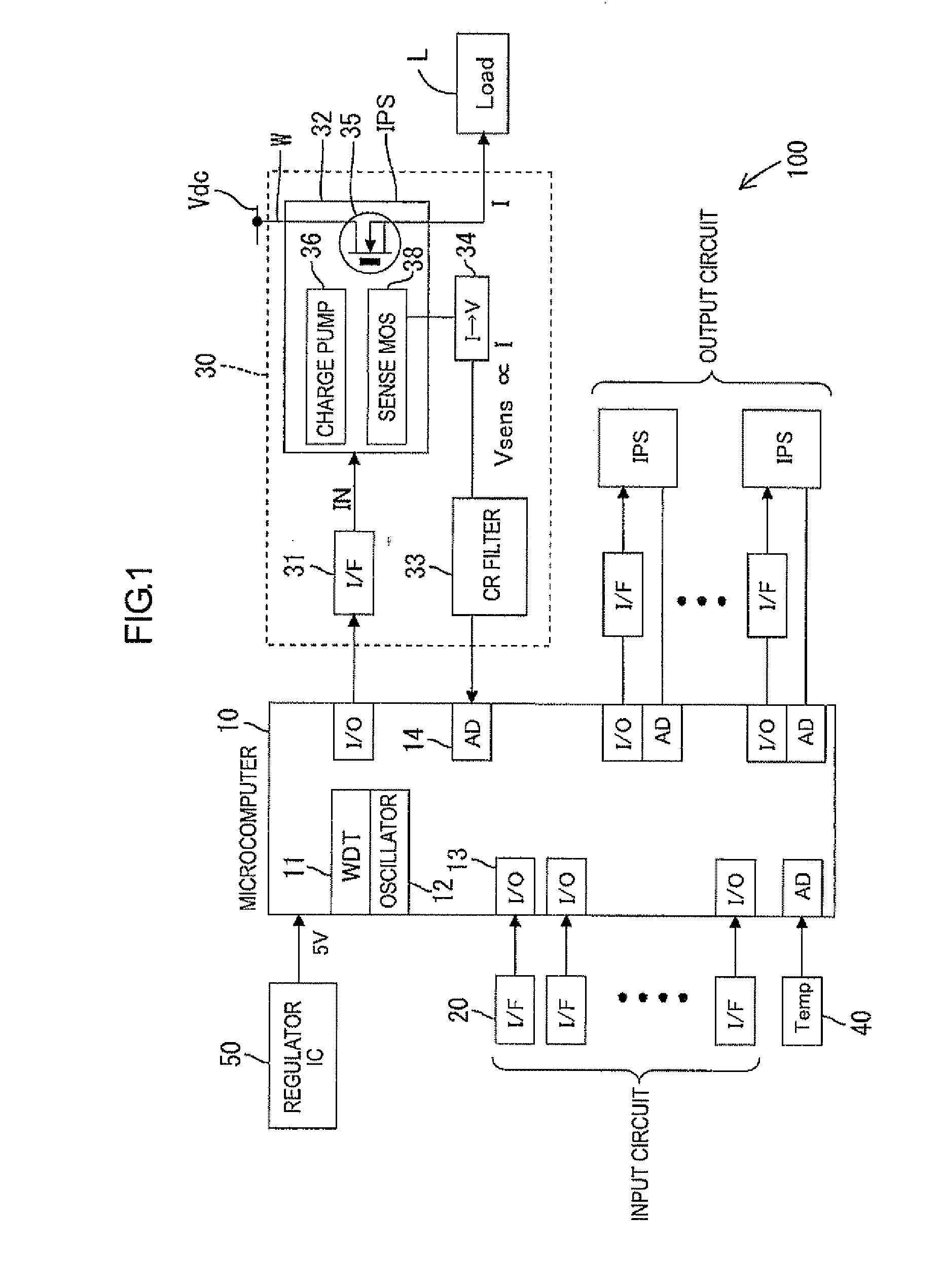
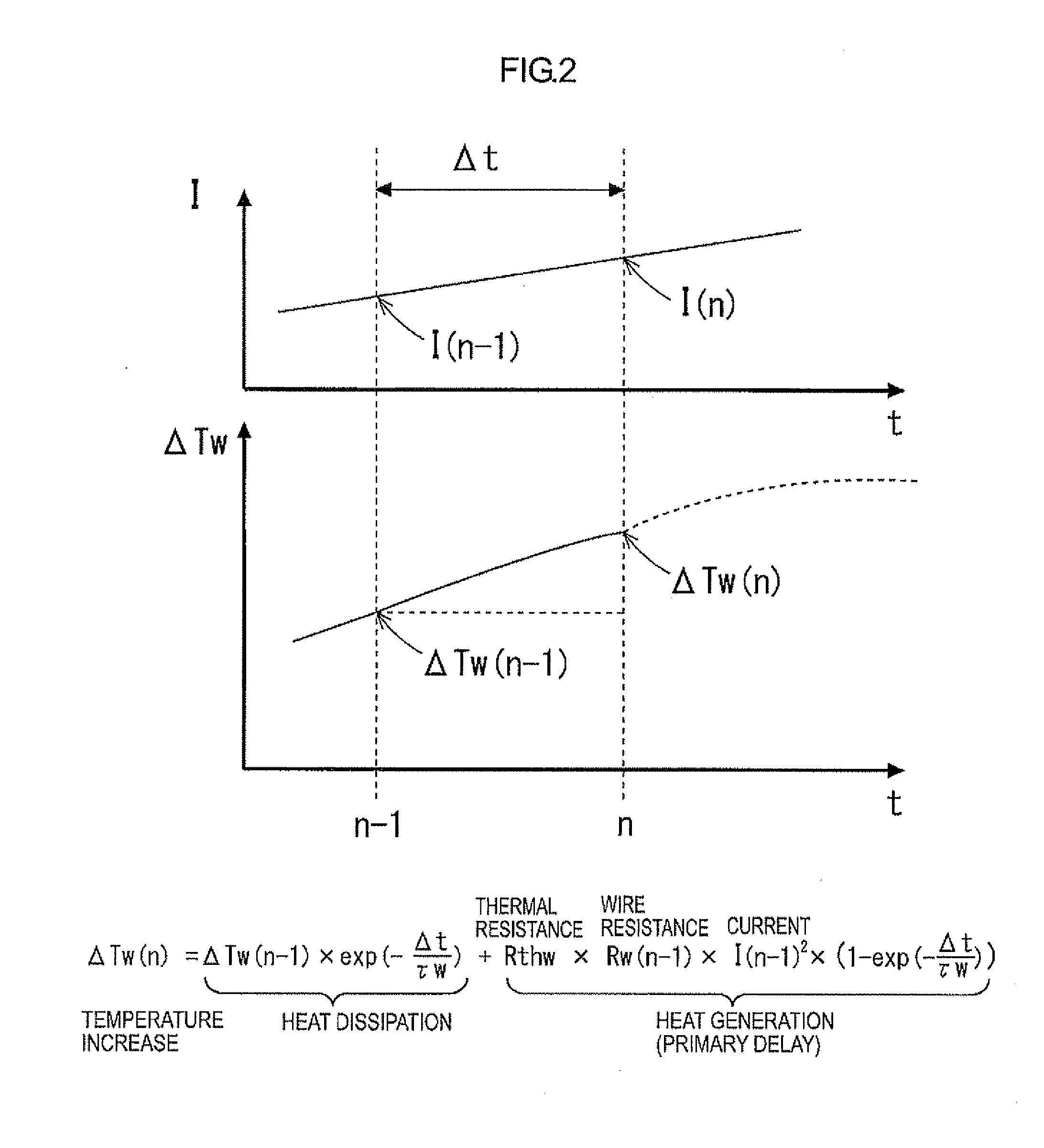
[0040]A description will be given of one embodiment of the present invention with reference to FIGS. 1 to 5.

A power supply controller 100 in the present embodiment is mounted in a vehicle (not shown), to control supply of power from a power source for use in the vehicle (hereinafter referred to as “power source Vdc”) to a load L. The load may come in, for example, a lamp in the vehicle, a cooling fan motor, or a defogging heater.

[0041]1. Overall Configuration of Power Supply Controller

[0042]FIG. 1 is a block diagram showing an outlined configuration of the power supply controller 100. The power supply controller 100 includes a semiconductor switch element 35 (for example, MOSFET; one example of “switch element”) to control supply of power from the power source Vdc to the load L by turning on and off the semiconductor switch element 35. The semiconductor switch element 35 is connected to a wire W (for example, wire harness; one example of “power supply path”) between the power source...


PUM


Abstract

The power supply controller performs the power-supply-path protection operation to restrict power supply through the switch element if a value of temperature increase of the power supply path W with respect to the reference temperature To exceeds the temperature threshold value and remove the restriction if the temperature decreases to the temperature threshold value or lower. And the controller performs the switch protection operation to restrict the power supply through the switch element if the value of the flowing current exceeds the current threshold value and remove the restriction after the reference time H elapses. And also the controller adds the additional value F to the value of temperature increase on condition that the value of the flowing current exceeds the current threshold value in the power supply protection operation and compares a post-addition temperature to the temperature threshold value.

Description

TECHNICAL FIELD[0001]The present invention relates to a power supply controller having a function to protect a switch element and a power supply path.BACKGROUND ART[0002]A power supply controller includes a switch element for permitting / inhibiting power supply from a power source to a load in order to control power supply to the load by turning the switch element on and off. In such a power supply controller, if an overcurrent flows, the switch element may burn out or a wire (power supply path) may smoke in some cases. Accordingly, a configuration is necessary in which if the overcurrent flows, the switch element would be held in the off-state to inhibit currents from flowing to the load, thereby protecting the switch element and the wire.[0003]Generally, a semiconductor switch and a wire are different from each other in terms of thermal characteristics (heat generation characteristics and heat dissipation characteristics), hence power supply inhibition conditions may be different f...

Claims


Application Information

Patent Timeline
Patent Type & Authority Applications(United States)
IPC IPC(8): G05F3/02
CPCH02H3/087H02H6/005H02M2001/327H03K17/08H02M1/32H02H7/226H02M1/327
Inventor HIGUCHI, YUTAKATAKAHASHI, SEIJI
Owner AUTONETWORKS TECH LTD
Learn More