Continuous tubular flow reactor and corrugated reactor tube for the reactor

a technology of continuous tubular flow and corrugated reactor tube, which is applied in the direction of chemical/physical/physical-chemical processes, transportation and packaging, chemical apparatus and processes, etc., can solve the problems of increasing pressure loss, complex mechanical structure, and difficult manufacture and installation of oscillatory flow reactors with orifice plates, and achieves simple harmonic motion driving and enhances the rate of chemical reaction

Inactive Publication Date: 2012-07-05
RESI CORP
View PDF10 Cites 30 Cited by
  • Summary
  • Abstract
  • Description
  • Claims
  • Application Information

AI Technical Summary

Benefits of technology

[0006]Another objective of the present invention is to provide a corrugated tube for the continuous tubular flow reactor, which provides a series of smooth convergent-divergent sections without dead space and provides extra mixing intensity when liquid flows through the corrugated tube.
[0007]According to the objectives mentioned above, the present invention provides a continuous tubular flow reactor which includes a reactor tube module having an inlet port and an outlet port and a pressuring device connected to the inlet and outlet ports of the reactor tube module. The reactor tube module includes multiple reactor tubes butt connected in sequence. Each reactor tube has alternating straight sections and convergent-divergent sections, wherein an inner diameter of the convergent-divergent section is smaller than that of the straight section. The pressuring device has a simple harmonic motion (SHM) driving device for providing the fluid a harmonic reciprocating flow in superposition to the original longitudinal flow. The present invention may provide a highly turbulent mixing condition without mechanical stirring device and enhance the rate of chemical reaction between liquid / liquid, liquid / gas, and liquid / solid phases.

Problems solved by technology

However, the manufacture and installation of oscillatory flow reactor with orifice plates is relatively difficult and the mechanical structure is complex as well.
Furthermore, the existence of orifice plates increases the pressure loss while the fluid flows through the reactor tube.

Method used


Image

  • Continuous tubular flow reactor and corrugated reactor tube for the reactor
  • Continuous tubular flow reactor and corrugated reactor tube for the reactor
  • Continuous tubular flow reactor and corrugated reactor tube for the reactor

Examples


Embodiment Construction

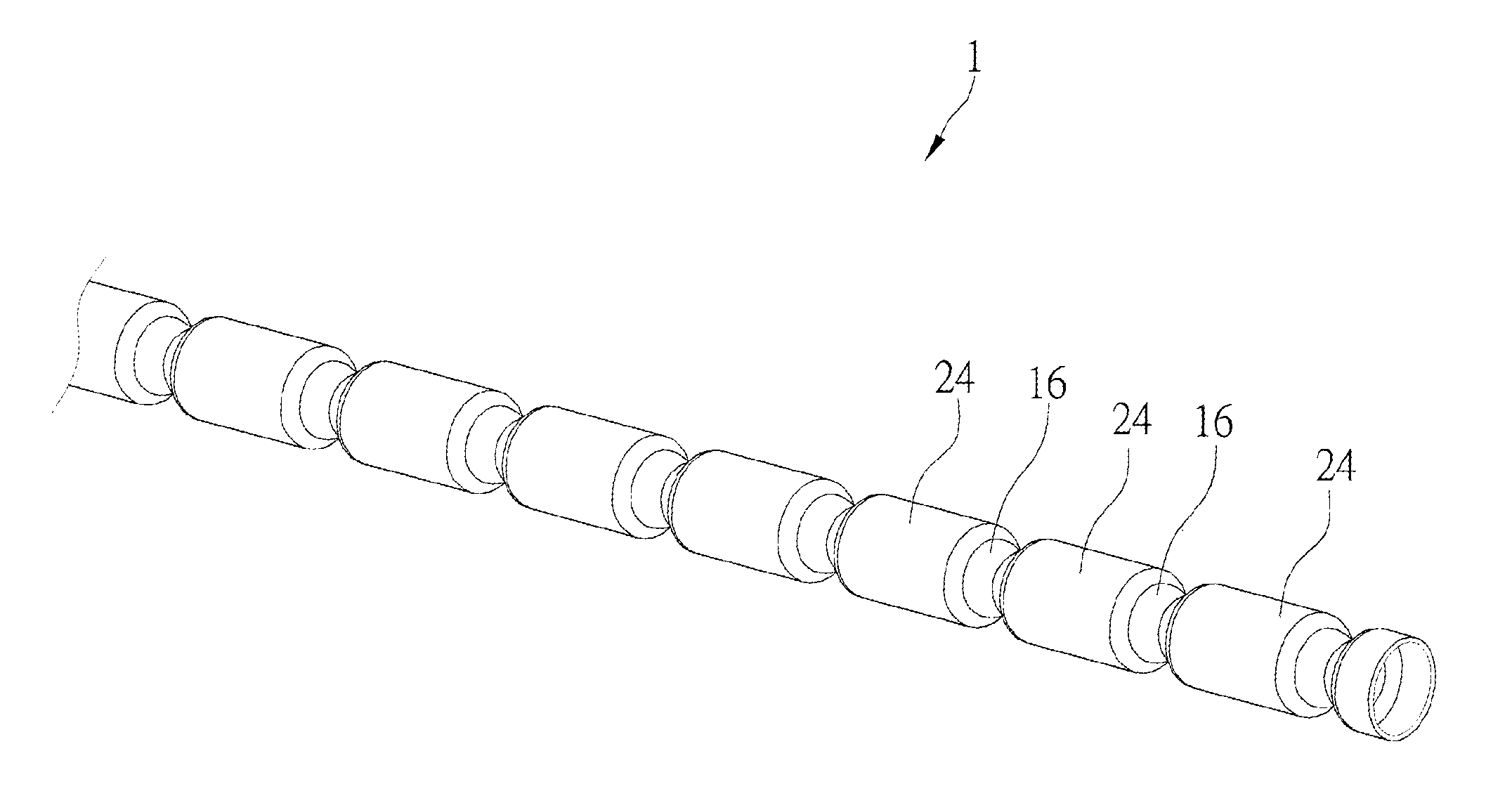
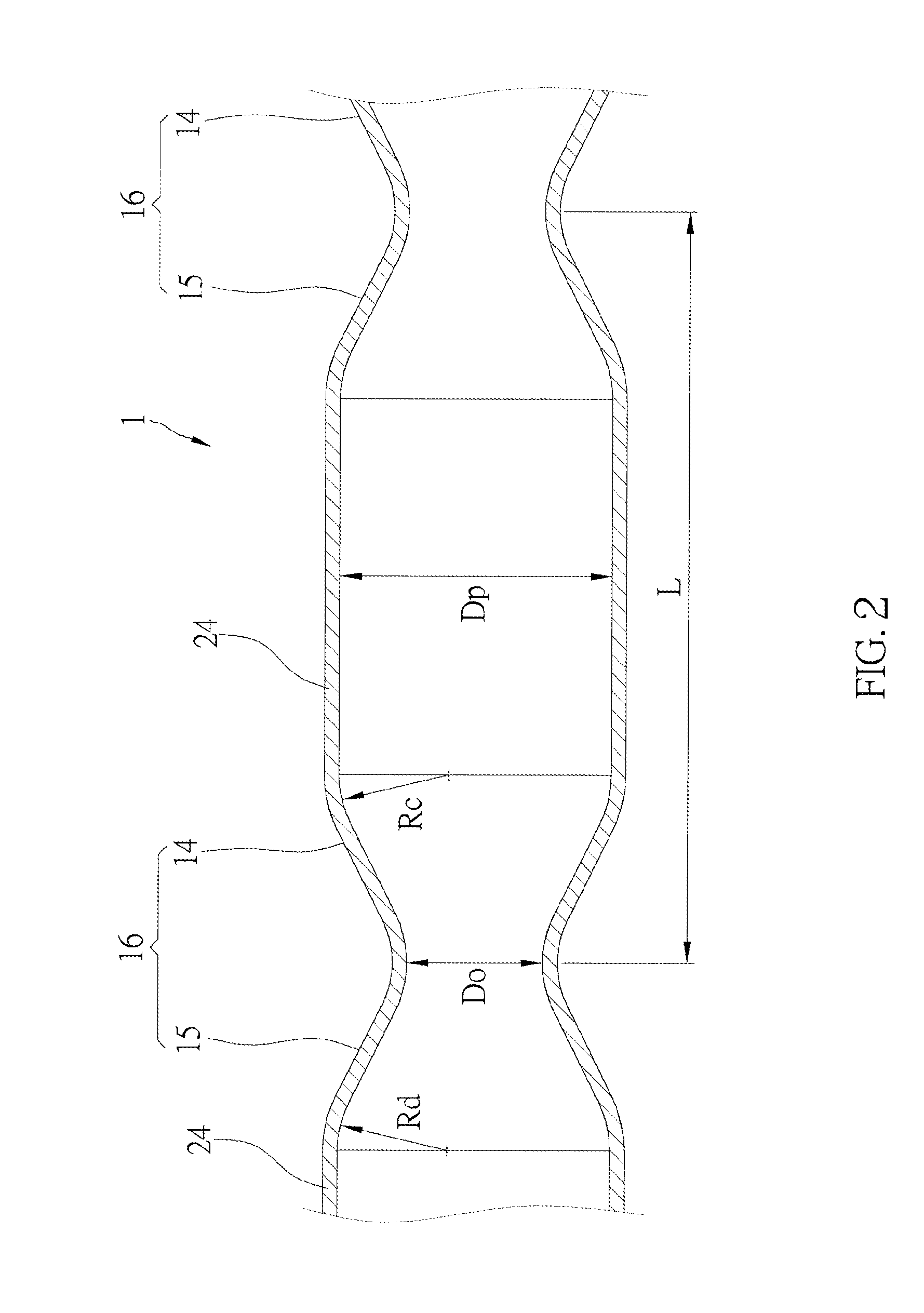
[0014]As shown in FIG. 1 and FIG. 2, a continuous tubular flow reactor of the preferred embodiment of the present invention includes a bundle of reactor tubes 1. The reactor tubes 1 may be made of metal, plastic, or glass. The reactor tube 1 has alternating straight sections 24 and convergent-divergent sections 16, wherein an inner diameter of the straight section 24 is larger than that of the convergent-divergent section 16. Each convergent-divergent section 16 consists of a convergent section 14 and a divergent subsection 15. The convergent subsection 14 has a gradually reducing inner diameter, and the divergent subsection 15 has a gradually increasing inner diameter. The inner diameter (Do) at a junction of the convergent subsection 14 and the divergent subsection 15 is shortest. The convergent subsection 14 and the divergent subsection 15 respectively have a curved sidewall, and they respectively have a radius of curvature (Rc represents the radius of curvature of the sidewall o...


PUM


Abstract

The present invention provides a continuous tubular flow reactor which consists of a reactor tube module having an inlet port and an outlet port, and a pressuring device connected to the inlet port and the outlet of the reactor tube module. The reactor tube module comprises multiple reactor tubes butt connected in sequence. Each reactor tube has alternating straight sections and convergent-divergent sections, wherein inner diameter of the convergent-divergent section is smaller than that of the straight section. The pressuring device has a simple harmonic motion driving device.

Description

BACKGROUND OF THE INVENTION[0001]1. Field of the Invention[0002]The present invention relates generally to a continuous tubular flow reactor, and more particularly to a continuous tubular flow reactor and a corrugated tube for the reactor, which may provide a highly turbulent mixing condition without a stirring device, and enhance the rate of chemical reaction between liquid / liquid, liquid / gas, and liquid / solid phases.[0003]2. Description of the Related Art[0004]Tubular reactor is widely used for various chemical reactions. Variety kinds of mixing devices, such as static mixer and sharp edged orifice plates, were developed for multi-phase reactions, especially for the reaction of volatile organic compounds, in an elevated pressure and temperature conditions, such as production of biodiesel. Taiwan patent M384866 taught a continuous oscillatory tubular flow reactor for production of biodiesel. The reactor provides a bundle of reactor tubes, with multiple orifice plates be inserted in...

Claims


Application Information

Patent Timeline
Patent Type & Authority Applications(United States)
IPC IPC(8): B01J8/04
CPCB01F5/0647B01F5/0655B01F11/0071B01F2215/0431B01J19/241B01J19/008B01J2219/00065B01J19/243B01J19/0053B01F25/4331B01F25/4338B01F31/65
Inventor CHANG, RON-HSIN
Owner RESI CORP
Why Eureka
Try Eureka