
Patient alert management system

a technology for alert management and patients, applied in healthcare informatics, instruments, healthcare resources and facilities, etc., can solve the problems of caregiver fatigue and confusion, difficult to determine exactly which location, and difficult to determine whether a single caregiver or multiple caregivers are needed,

Inactive Publication Date: 2012-07-05
AMPLION CLINICAL COMM
View PDF11 Cites 54 Cited by
  • Summary
  • Abstract
  • Description
  • Claims
  • Application Information

AI Technical Summary

Problems solved by technology

With the myriad patient care devices (e.g., drug pumps, food pumps, blood pressure monitors, pulse / oxygen monitors, pressure pads, etc.) used in each patient room, caregivers suffer from alarm (i.e., alert) fatigue and confusion.
It is often difficult to determine exactly which location (e.g., room) an alarm is emanating from and what the alarm means.
Thus, it is hard to determine whether a single caregiver or multiple caregivers, and what type of caregivers are needed at the location.
Unfortunately, these records are often incomplete, inaccurate, or falsified to show that care was provided to a patient when in fact, no care, or inappropriate care was provided.
Frequently, items like checking whether pain medication is sufficient one hour after administration and turning patients at a set interval are not performed consistently.
Further, it is difficult to gather performance statistics from these charts for analyzing care efficiencies in the hospital or caregiving facility or for analyzing patient data for indications of certain medical conditions.
Existing methods of communication between caregivers are also noisy and unidirectional.
The healthcare staff at the nursing station has no way of knowing whether the intended caregiver has received the page and when or if the caregiver attended to the patient's need.

Method used


Image

  • Patient alert management system
  • Patient alert management system
  • Patient alert management system

Examples


Embodiment Construction

[0027]While the making and using of various embodiments of the present invention are discussed in detail below, it should be appreciated that the present invention provides many applicable inventive concepts that can be embodied in a wide variety of specific contexts. The specific embodiments discussed herein are merely illustrative of specific ways to make and use the invention and do not delimit the scope of the invention.

[0028]To facilitate the understanding of the embodiments described herein, a number of terms are defined below. The terms defined herein have meanings as commonly understood by a person of ordinary skill in the areas relevant to the present invention. Terms such as “a,”“an,” and “the” are not intended to refer to only a singular entity, but rather include the general class of which a specific example may be used for illustration. The terminology herein is used to describe specific embodiments of the invention, but their usage does not delimit the invention, excep...


PUM


Abstract

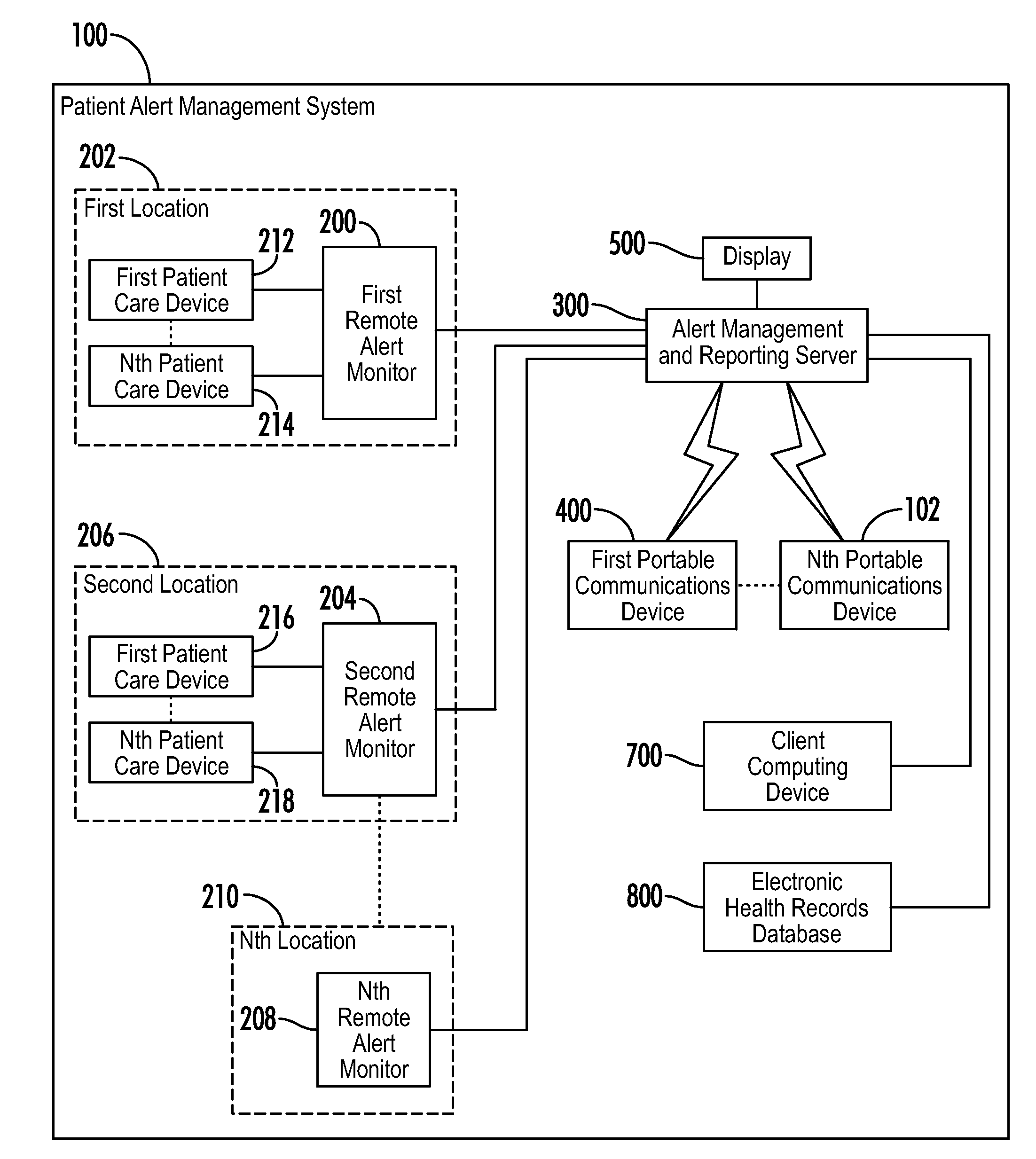
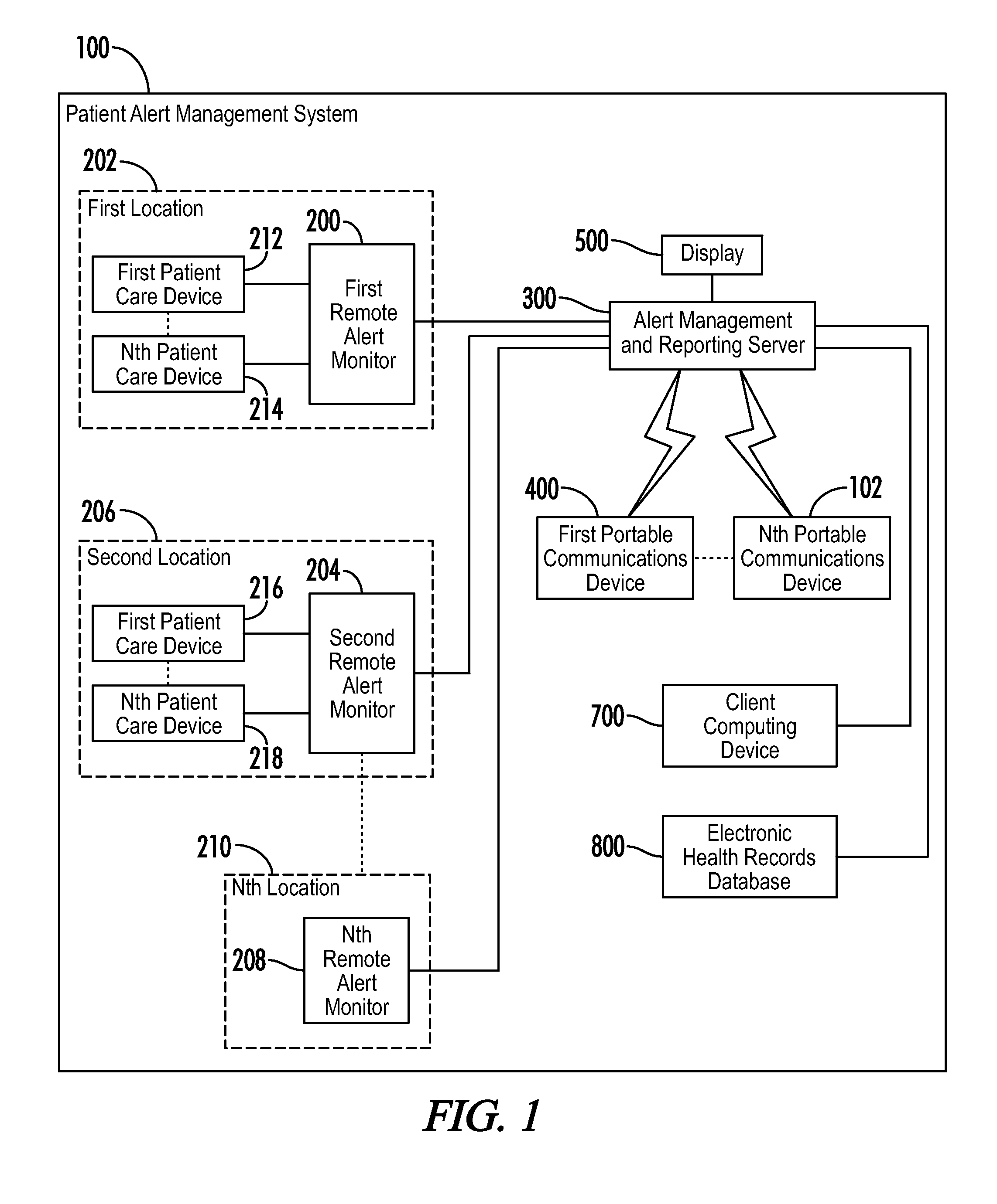
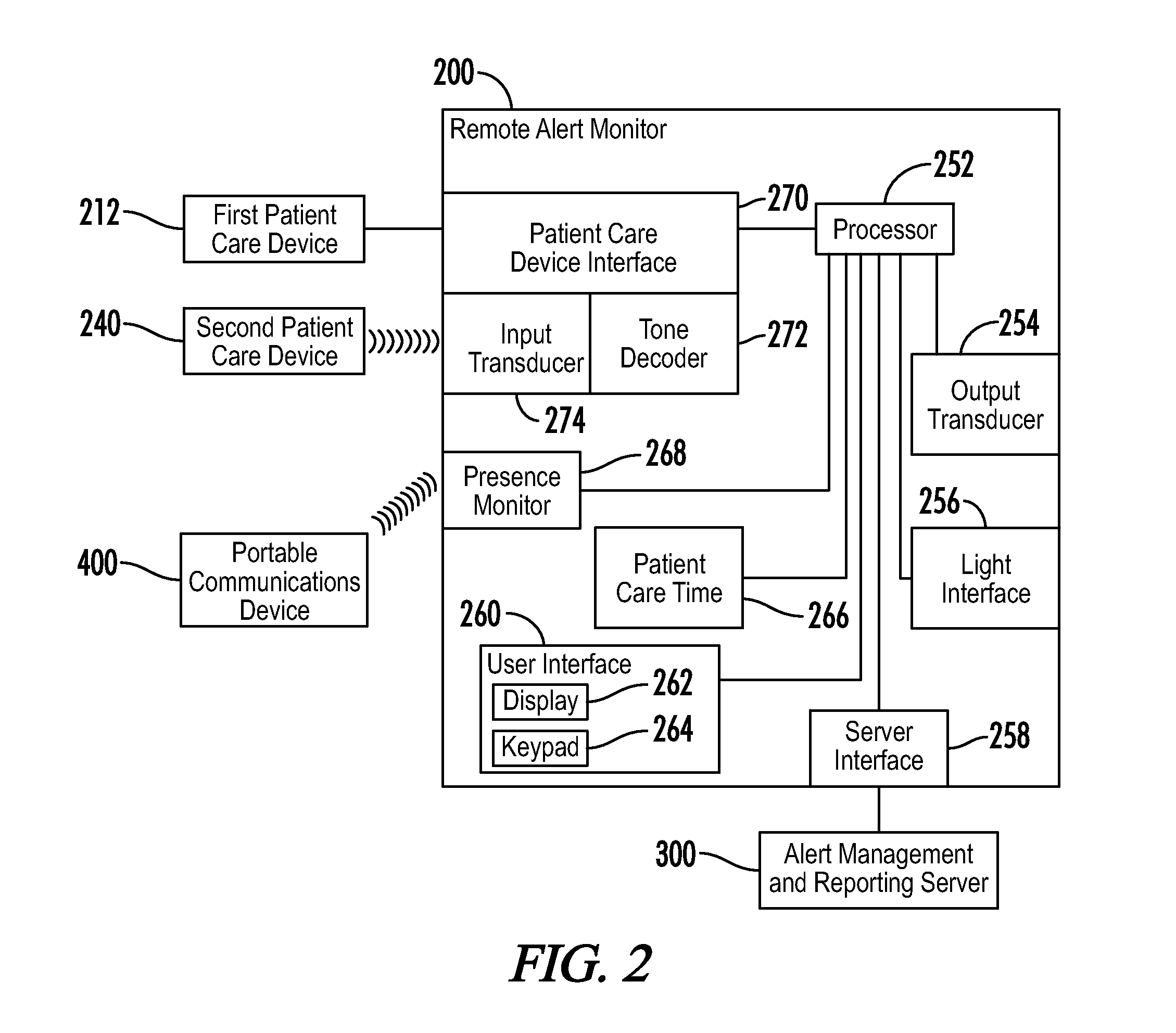
A patient alert management system includes a remote alert monitor at a location, an alert management and reporting server, and a portable communications device. The remote alert monitor generates an alert in response to an internal patient care timer or receiving an alert from a patient care device at the location of the remote alert monitor and communicates the alert to the alert management and reporting server. The alert management and reporting server sends a message to the portable communications device including a description of the alert and the location. The portable communications device displays the description and location to a caregiver. The caregiver goes to the location and cancels the alert via the remote alert monitor. The remote alert monitor sends an alert cancellation to the alert management and reporting server in the alert management and reporting server cancels the alert in response to receiving the alert cancellation.

Description

[0001]A portion of the disclosure of this patent document contains material that is subject to copyright protection. The copyright owner has no objection to the reproduction of the patent document or the patent disclosure, as it appears in the U.S. Patent and Trademark Office patent file or records, but otherwise reserves all copyright rights whatsoever.CROSS-REFERENCES TO RELATED APPLICATIONS[0002]This application claims benefit of the following patent application which is hereby incorporated by reference in its entirety: U.S. Provisional Patent Application No. 61 / 428,948, filed Dec. 31, 2010 entitled “REMOTE MONITORING SYSTEM FOR HOSPITAL PATIENTS.”STATEMENT REGARDING FEDERALLY SPONSORED RESEARCH OR DEVELOPMENT[0003]Not ApplicableREFERENCE TO SEQUENCE LISTING OR COMPUTER PROGRAM LISTING APPENDIX[0004]Not ApplicableBACKGROUND OF THE INVENTION[0005]The present invention relates to systems, methods and devices for monitoring hospital patients electronically and for managing alerts ge...

Claims


Application Information

Patent Timeline
IPC IPC(8): G08B5/22
CPCG06F19/3418G08B25/001G06F19/3487G16H15/00G16H40/20G16H40/67
Inventor CONDRA, DAVID L.
Owner AMPLION CLINICAL COMM
Learn More