Urinal drain trap

a technology for drain traps and urinals, applied in urinals, water installations, construction, etc., can solve the problems of reducing the amount of sealing liquid and thinning the sealing layer, clogging the ascending flow path, and foul odor of collected urine, so as to prevent the occurrence of siphon action, prevent the flow path area of the outflow conduit, and prevent the effect of siphon action

Inactive Publication Date: 2012-07-05
LIXIL CORP
View PDF2 Cites 15 Cited by
  • Summary
  • Abstract
  • Description
  • Claims
  • Application Information

AI Technical Summary

Benefits of technology

[0024]Accordingly, the urinal drain trap according to the invention can desirably drain urine for a long period of time.
[0025]The outflow conduit may have a larger flow passage area than the ascending flow path defined by the outer surface of the outflow conduit and the inner surface of the partition wall as the second region is viewed in a top cross-section. In this case, since a flow rate of urine that can flow through the outflow conduit is larger than a flow rate of the urine that can flow through the ascending flow path, the outflow conduit can be prevented from being full of urine flowing through the ascending flow path. This can prevent a siphon action caused by the outflow conduit full of urine. In other words, urine that should remain in the urinal drain trap can be prevented from being discharged due to occurrence of a siphon action, whereupon water seal can be prevented from disappearing. Furthermore, even when gel urinary calculi are accumulated on the inner surface of the downstream side of the outflow conduit, the situation can be retarded where the outflow conduit is full of urine flowing through the ascending flow path. Consequently, the urinal drain trap can desirably be used for a long period of time.
[0026]The partition wall may be formed so as to extend from a middle portion of the body toward an inner peripheral surface of the sidewall as the partition wall is viewed in a top cross-section. In this case, the flow path area of the outflow conduit can further be increased. Consequently, the outflow conduit can be prevented from being full of urine flowing through the ascending flow path, and occurrence of a siphon action can be prevented. Furthermore, the situation can be retarded where gel urinary calculi are accumulated on the inner surface of the downstream side of the outflow conduit thereby to reduce the flow path area such that the outflow conduit is full of urine having flowed from the ascending flow path. Consequently, the urinal drain trap can desirably be used for a long period of time.
[0027]The partition wall may be formed into a cylindrical shape, and the outflow conduit may be formed into a semi-circular cylindrical shape and disposed so that an arc-shaped outer surface thereof is located near the inner surface of the partition wall. In this case, the flow path area of the outflow conduit can be increased while the space can be increased between the outer surface of the outflow conduit and the inner surface of the partition wall at the other side in the partition wall in planar view. This can ensure a sufficient amount of urine flowing from the outflow conduit, whereupon urine can desirably be discharged.
[0028]The third region may have a vertical dimension that is larger than a transverse dimension of a descending flow path of urine formed in the first region and the ascending flow path of urine in a vertically middle section. In this case, since the vertical dimension of the third region where gel urinary calculi are easily accumulated can be increased, the third region can be prevented from being early clogged even when gel urinary calculi accumulate in the third region.
[0029]A drain conduit is connected to the urinal drain trap and the trap may be formed into a cartridge type so as to be detachably attached to a recess that is upwardly open in the lower end of the urinal bowl surface. In this case, the whole cartridge can be changed to another when an amount of the sealing liquid is reduced or when accumulation of gel urinal calculi results in the clogging. Consequently, maintenance can easily be carried out. Furthermore, since the clogging of the urinal drain trap due to accumulation of gel urinal calculi is suppressed, an exchange frequency of the cartridge can be reduced.

Problems solved by technology

Consequently, long-term use of the urinal drain trap results in gradual flow of the sealing liquid out of the outlet, reducing an amount of the sealing liquid and thinning the sealing layer.
When the sealing layer is thinned, there is a possibility that foul odors of collected urine may be produced out of the inlet.
When the space between the outer surface of the outlet conduit and the inner surface of the partition wall is narrow, the gel urinary calculi adherent to the outer surface of the outlet conduit and the inner surface of the partition wall accumulate, there is a possibility that the ascending flow path may early be clogged.

Method used


Image

  • Urinal drain trap
  • Urinal drain trap
  • Urinal drain trap

Examples


embodiment 1

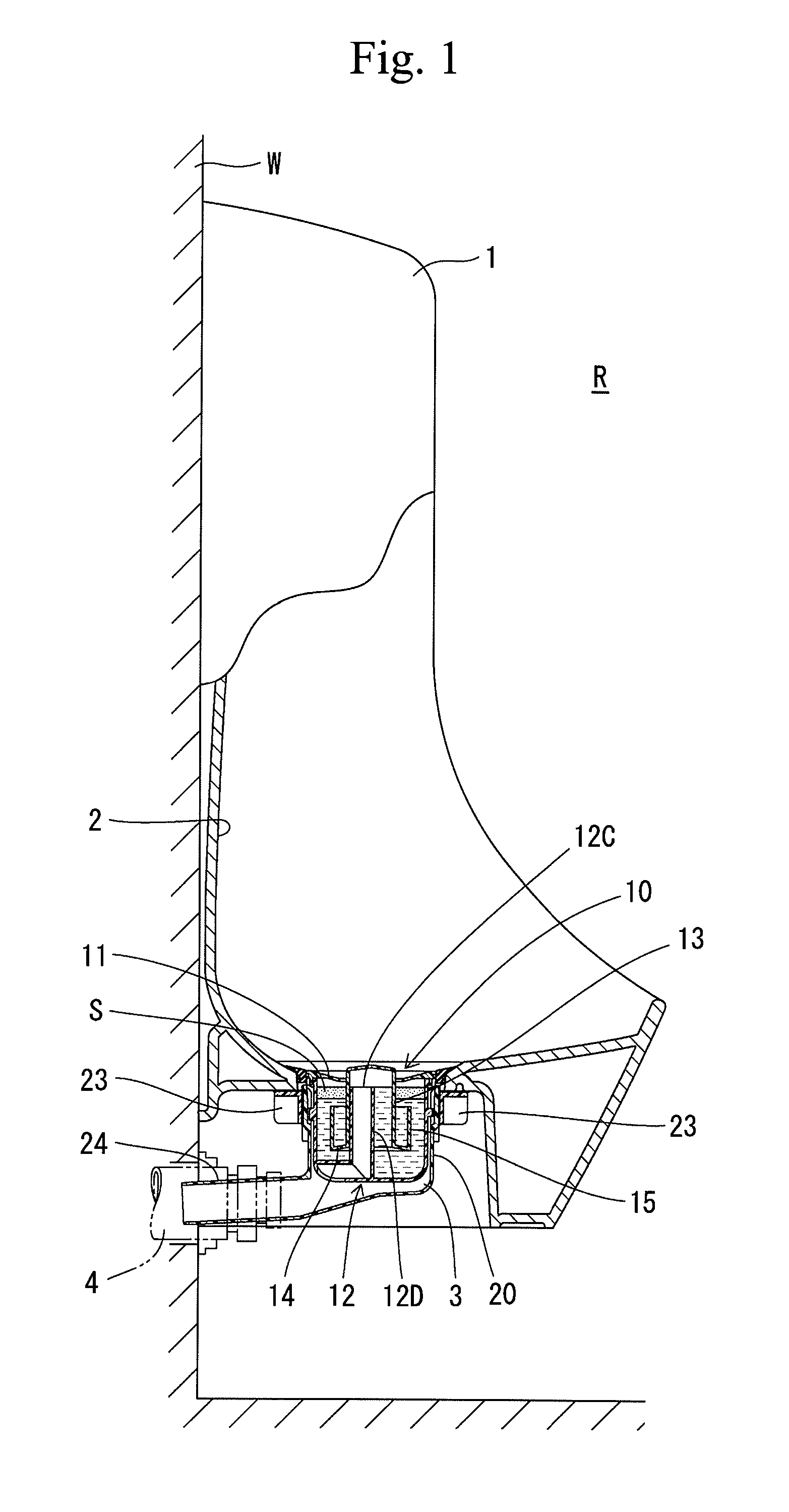
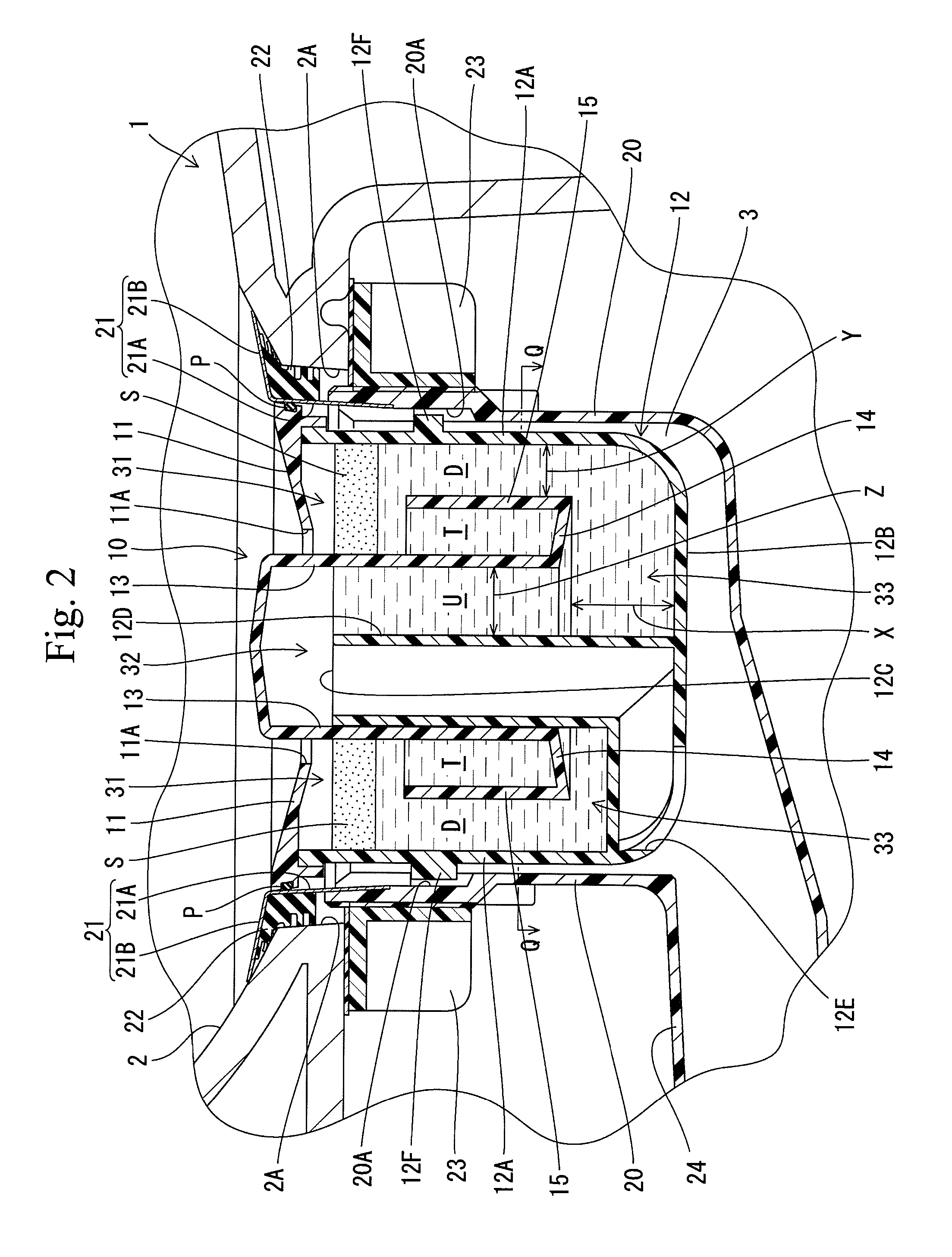
[0043]The urinal drain trap 10 according to embodiment 1 is formed into a cartridge type and detachably mounted in a recess 3 which is upwardly open at a lower end of a bowl surface 2 of a urinal 1 as shown in FIGS. 1 to 3 and 4A. The urinal 1 is of a wall-mounted type and is fixed to a wall surface W of a toilet room R. The recess 3 is formed into a cylindrical storage container 20 which is mounted on a lower end of the bowl surface 2 of the urinal 1 and has an open upper end and a bottom.

[0044]The storage container 20 has an upper end to which a locking member 21 is connected. The locking member 21 is connected to an upper part of an inner surface of the storage container 20 and includes an upwardly extending cylindrical portion 21A and a ring-shaped flange 21B spreading outward from an upper end of the cylindrical portion 21A. A locking recess 20A is formed in a middle part of the inner surface of the storage container 20. A locking convexity 12F provided on a sidewall 12A of a b...

embodiment 2

[0068]The urinal drain trap 110 according to embodiment 2 includes a body 112 directly mounted on a lower end of the bowl surface 2 of the urinal 1 as shown in FIG. 5. The locking member 21 is connected to the upper end of the body 112. The body 112 is inserted from above into the opening 2A formed in the lower end the bowl surface 2, so that the flange 21B of the locking member 21 is locked by an upper surface of the peripheral portion of the opening 2A. A threaded portion is formed in an upper part of the outer surface of the body 112. The ring-shaped fastening member 23 is fitted with the body 112 from below and has an upper surface which is locked to the underside of the peripheral edge of the opening 2A. The fastening member 23 is screwed into the threaded portion formed in the outer surface of the body 112. The peripheral edge of the opening 2A is thus held between the flange 21B of the locking member 21 and the fastening member 23, whereby the body 112 is mounted in the openi...

embodiment 3

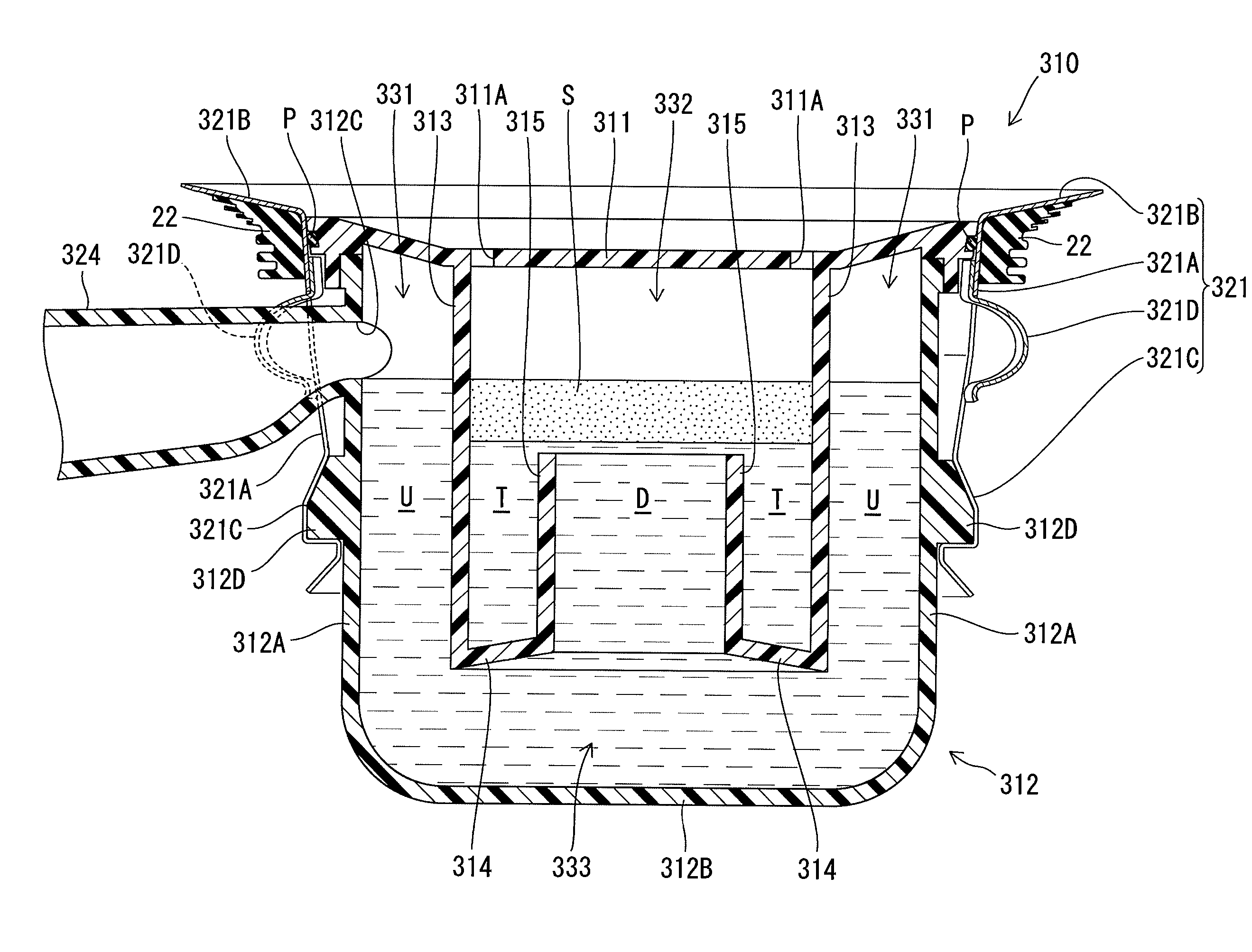
[0075]In the urinal drain trap 210 according to embodiment 3, the outflow conduit 212D is formed into a cylindrical shape and is coaxial with the sidewall 212A of the body 212 as shown in FIG. 6. The outflow conduit 212D is also coaxial with the partition wall 13. As a result, the urine ascending flow path U is defined between the periphery of the outflow conduit 212D and the partition wall 13. The drain hole 212E facing the upstream portion of the connecting conduit 24 of the storage container 20 is formed in a central part of the bottom 212B of the body 212. The other construction of the urinal drain trap 210 according to the embodiment 3 is the same as that according to the embodiment 1. Identical parts in the embodiment 3 are labeled by the same reference symbols as those in the embodiment 1 and detailed description of these parts will be eliminated.

[0076]In the urinal drain trap 210 having the above-described construction, too, much of the sealing liquid drawn below the sealing...


PUM


Abstract

Provided is a urinal drain trap which is capable of preventing diffusion of odor for a long period of time. The urinal drain trap (10) is equipped with a lid (11) having an inlet (11A); a body (12) having an outlet (12C); and a tubular partition wall (13). The interior of the body (12) is divided into a first region (31) and a second region (32). The first region (31) and the second region (32) are linked with each other by a third region (33). Sealing liquid is injected into the first region (31), this sealing liquid being non-water-soluble, having a lower specific gravity than urine, and forming a sealing layer (S) at an elevation above retained urine. In a peripheral area of the lower end of the partition wall (13), there is formed a connecting portion (14) which extends laterally. In a peripheral area of the tip of the connecting portion (14), there is formed a folded portion (15) which extends upward. Between the partition wall (13) and the folded portion (15), the inlet (11A) is provided, in such a way as to form a through opening, at a location where urine flows in from above. The outlet (12C) is located in the second region (32) and is open at an elevation above the upper end of the folded portion (15).

Description

TECHNICAL FIELD[0001]The present invention relates to a urinal drain trap.BACKGROUND ART[0002]FIG. 12 of Patent Document 1 discloses a conventional urinal drain trap. The urinal drain trap is formed into a cartridge type and includes a lid, a body and a partition wall. The urinal drain trap is fitted into a circular opening defined in a lower end of a bowl surface of the urinal thereby to be mounted to the urinal. The lid has a circular shape as viewed in a planar view. The lid has a central part formed with an inlet through which urine flowing downwards along the bowl surface further flows into the trap. The body includes a cylindrical sidewall extending downward from an outer peripheral edge of the lid, a bottom continuous from a lower end of the sidewall, and an outlet over which collected urine flows. The partition wall extends downward from a part of the underside located on the inward side relative to the outer peripheral edge of the lid and is formed so as to define a space t...

Claims


Application Information

Patent Timeline
Patent Type & Authority Applications(United States)
IPC IPC(8): E03D13/00
CPCE03C1/29E03C1/281E03C1/28E03D13/00
Inventor NOMURA, KAZUTERUKITAMURA, SATOSHIYAMASAKI, HARUOKONDO, AKIKOHANDA, SHUHEINAKAYAMA, YUJICHAYA, KAZUHISA
Owner LIXIL CORP
Why Eureka
Try Eureka