[0010] In accordance with the present invention, a bicycle wheel includes a tire engaging portion located at the outward perimeter of the wheel, an inner portion located radially inward from the tire engaging portion, and a pair of air engaging side surfaces extending radially between the inner portion and the tire engaging portion forming the sides of the wheel. The air engaging side surfaces contain a plurality of surface features designed to create a turbulent boundary layer when the wheel travels through air to reduce
aerodynamic drag on the wheel.
[0011] Drag is the air resistance that exerts itself in the direction opposite to the wheel's direction of movement, and thus the bicycle's direction of movement. As the wheel travels through the air, the air that surrounds the wheel has different velocities and thus, different pressures. The air exerts
maximum pressure at a
stagnation point on the front of the wheel. The air then flows around the side surfaces of the wheel with an increased velocity and reduced pressure. At some separation point, the air separates from the side surfaces of the wheel and generates a large turbulent flow area
behind the wheel. This flow area, which is called the wake, has low pressure. The difference between the
high pressure at the front of the wheel and the low pressure
behind the wheel slows the wheel and the bicycle down. This is the
primary source of drag for the bicycle wheel.
[0012] All objects moving through air have a
thin layer, called the boundary layer, of air surrounding them. The object shapes range from blunt to streamlined. Blunt objects create large wakes behind them that in turn create greater drag. More streamlined objects create a smaller wake and therefore less drag. The surface features on the wheel cause a thin boundary layer of air adjacent to the wheel's outer surface to become turbulent. This turbulence energizes the boundary layer and helps keep it attached to the sides of the wheel longer, thus moving the separation point further backward on the wheel which reduces the size of the wake
behind the wheel creating a more streamlined and aerodynamic air flow. As a result, there is a reduction in the area of the wake behind the wheel which increases the pressure behind the wheel, and substantially reduces the
aerodynamic drag. It is the surface features on the wheel of the present invention that creates the turbulence in the boundary layer and reduces the aerodynamic drag.
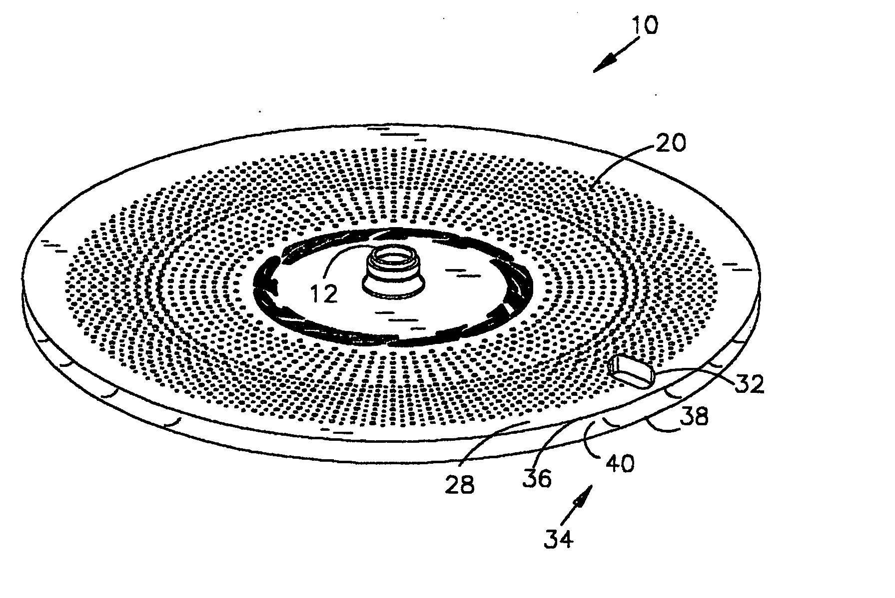
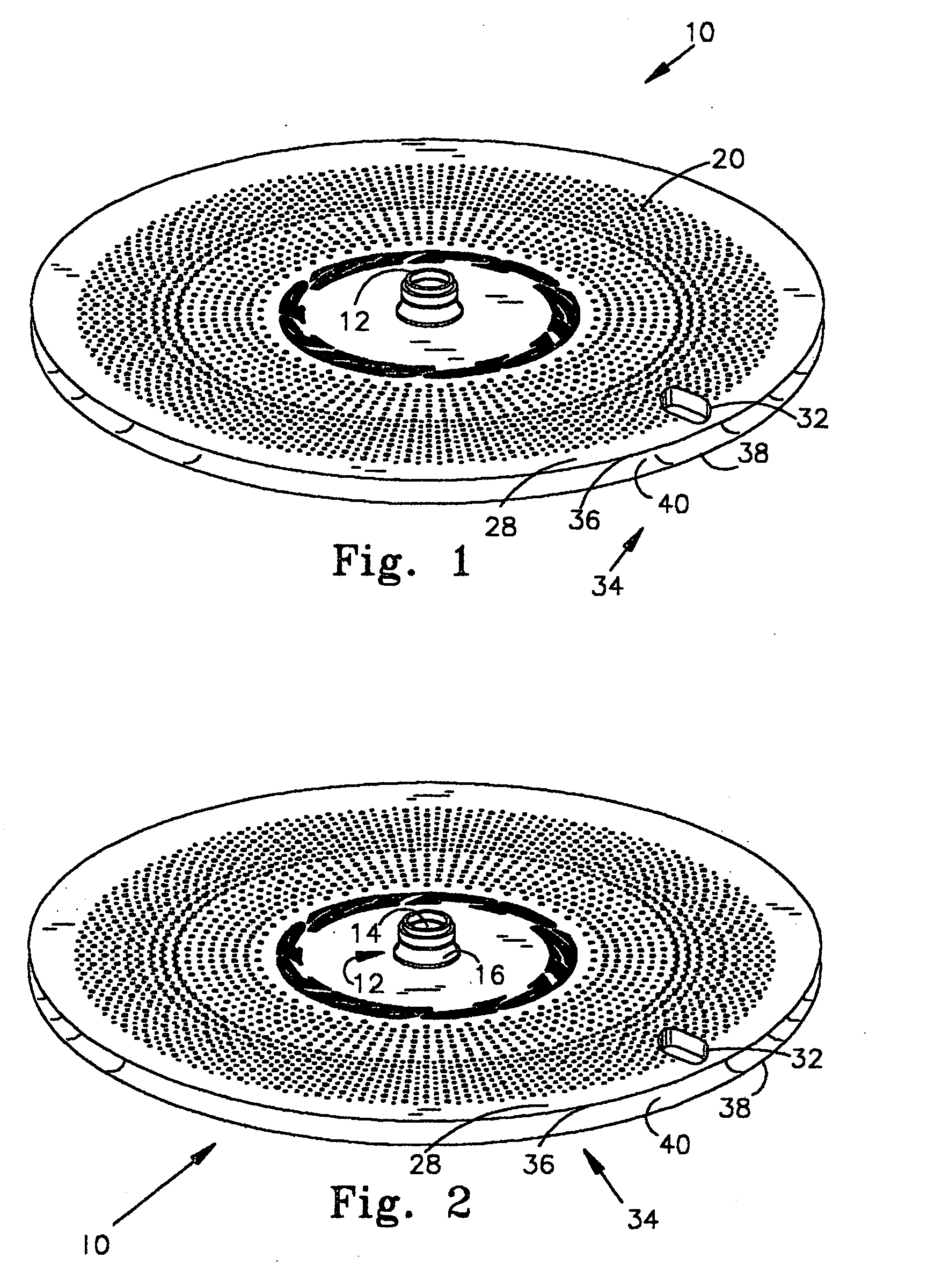
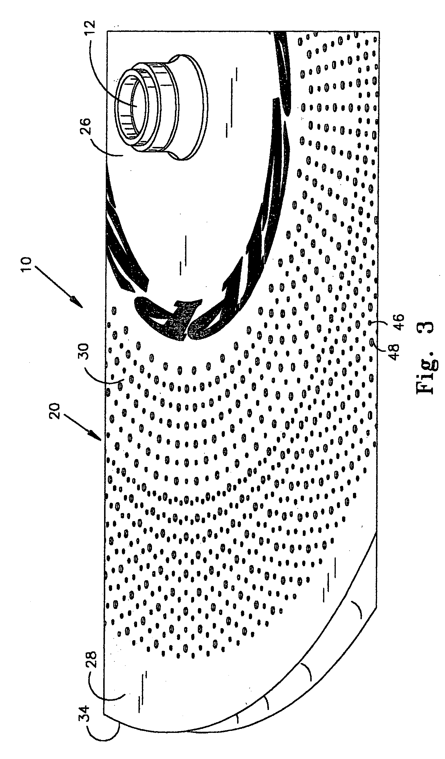
[0015] One feature of the present invention is that it includes, on its air engaging surface, an array of surface features such as
dimple-shaped depressions. The
dimple-shaped depressions provide two advantages, with the first being aerodynamic, and the second being structural. With respect to the aerodynamic advantages, the covering of dimples on the air engaging surface creates a
thin layer of air next to the wheel, the boundary layer. This boundary layer of air becomes turbulent in its flow patterns over the surface features of the air engaging surfaces. Rather than flowing in smooth continuous
layers over the air engaging surface, the dimples cause the air to have a microscopic pattern of fluctuations and randomized flow. This "turbulence" in the boundary layer enables the air flowing around the air engaging surface to better follow the surface of the air engaging surface, and enables the air to travel further along the air engaging surfaces of the wheel. This creates a much smaller wake at the "down
stream end" of the wheel. This reduced wake results in a significant reduction in the aerodynamic drag of the wheel.
[0016] The use of surface depressions, such as an array of dimpled depressions or radially extending depressions, can also provides structural advantages to the wheel, especially a disc-type wheel. A disc-type wheel generally includes an air engaging surface that extends continuously between the hub at the center of the wheel, and a tire-engaging portion at the radially outward perimeter of the wheel. As such, the first and second air engaging surfaces in prior wheels comprise smooth circular planes having a
diameter that is usually in a range of 26 or 27 inches. Although the
carbon fiber composite material from which disc wheels such as the ZIPP.RTM. 900 Disc Wheel are made is very rigid, it will be appreciated that any large planar body, such as a disc wheel, upon which radially and axially directed forces are exerted, may be induced to flex or bow. An array of surface features placed on the air engaging surfaces which protrude into and / or extend out of the major plane of the air engaging surfaces of a wheel can increase the rigidity of the wheel, and enhance the resistance of the wheel to flexing movements.
