
Plasma enhanced chemical vapor deposition apparatus

a technology enhanced plasma, which is applied in the direction of chemical vapor deposition coating, coating, plasma technique, etc., can solve the problems of reducing the efficiency of the process, including the deposition rate and materials usage, to the degree of electrode coating, and reducing the buildup of coating on the magnetron. , the effect of long pecvd coating runs

Inactive Publication Date: 2012-06-28
GENERAL PLASMA
View PDF34 Cites 27 Cited by
  • Summary
  • Abstract
  • Description
  • Claims
  • Application Information

AI Technical Summary

Benefits of technology

[0008]In the embodiments of the invention, coating buildup on the magnetron is minimized and long PECVD coating runs are made possible. The configurations of the embodiments of the invention PECVD deposition on large area substrates are particularly benefited and long, continuous PECVD processes are enabled.

Problems solved by technology

PECVD has not been more widely used owing to the coating not just on the substrate where it is wanted, but also on other surfaces including critical electrode surfaces of the plasma source.
If the coating is non-conducting, the operating characteristics of the plasma source become an operational dynamic that inhibits coating uniformity in commercial production.
Coating buildup on the magnetron electrode(s) causes severe process difficulties: The electrical circuit impedance varies with the buildup affecting process stability and the efficiency of the process, including the deposition rate and materials usage, is reduced to the degree of electrode coating.
In prior art PECVD apparatus, while useful coatings may be deposited on the substrate, the source is quickly coated causing process drift and arcing.
In these applications an etch cleaning cycle is not practical.

Method used


Image

  • Plasma enhanced chemical vapor deposition apparatus
  • Plasma enhanced chemical vapor deposition apparatus
  • Plasma enhanced chemical vapor deposition apparatus

Examples


Embodiment Construction

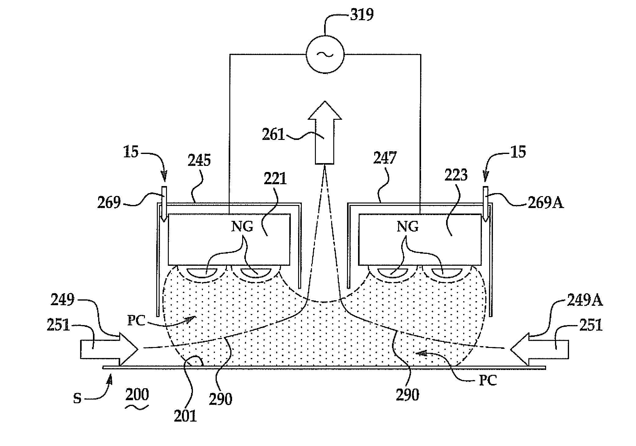
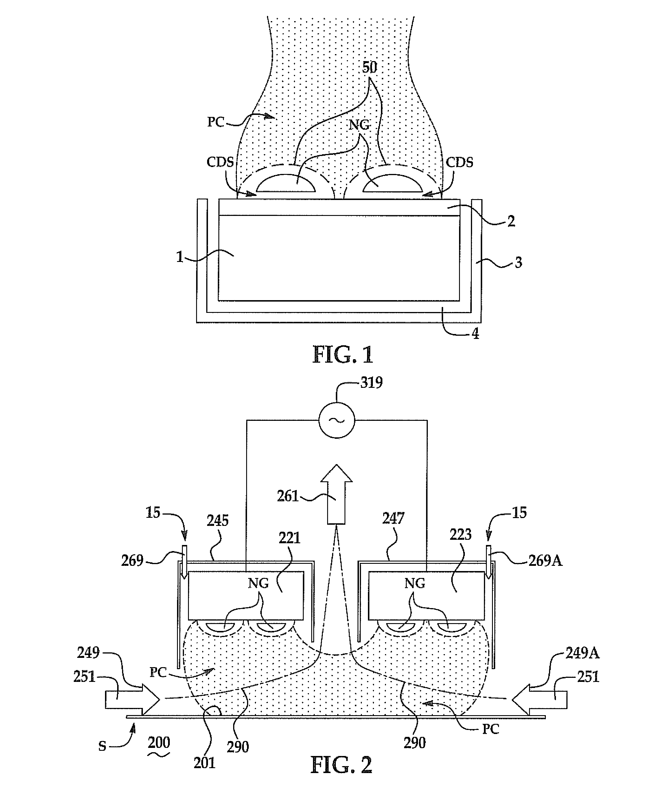
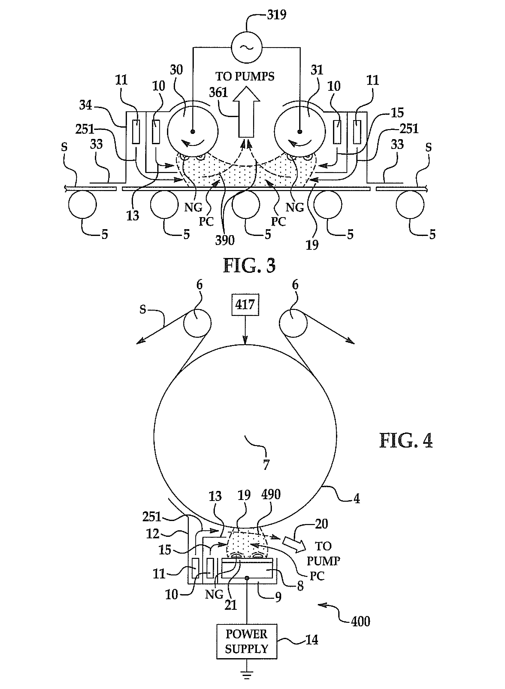
[0024]The present invention has utility in the plasma enhanced chemical vapor deposition (PECVD) of volatile precursors onto a substrate. The present invention largely overcomes the prior art problem of electrically insulating coatings building up on deposition electrodes by preferentially injecting precursor gas into the positive column and adjacent to a deposition substrate, such that the negative glow region is exposed to a limited amount of precursor so as to limit coating growth onto the magnetron target proximal to the negative glow region.

[0025]In each of the embodiments shown and described hereinafter, the process chamber, magnetron plasma source, precursor gas inlet, and pump outlet are configured to provide a flow path or flow paths that preferentially channel injected CVD precursor gas into the plasma source positive column adjacent the substrate such that precursor gas interaction with the lobular areas defining the negative glow regions is disfavored and substantially e...


PUM

PropertyMeasurementUnit
Timeaaaaaaaaaa
Flow rateaaaaaaaaaa
Lengthaaaaaaaaaa

Abstract

PECVD apparatus for depositing material onto a moving substrate is provided comprising a process chamber, a precursor gas inlet to the process chamber, a pumped outlet, and a plasma source disposed within the process chamber. The plasma source produces one or more negative glow regions and one or more positive columns. At least one positive column is disposed toward the substrate. The plasma source and precursor gas inlet are disposed relative to each other and the substrate such that the precursor gas is injected into the positive column adjacent the substrate. Apparatus is provided to channel the precursor gas into the positive column away from the negative glow region.

Description

CROSS-REFERENCE TO RELATED APPLICATION[0001]This application claims priority of U.S. Provisional Patent Application Ser. No. 61 / 275,930, filed Sep. 5, 2009, which is incorporated herein by reference.FIELD OF THE INVENTION[0002]The present invention relates to plasma enhanced chemical vapor deposition (PECVD) apparatus and processes.BACKGROUND OF THE INVENTION[0003]Plasma enhanced chemical vapor deposition (PECVD) is a process used to deposit thin films from a gas state (vapor) precursor to a solid state coating on a substrate. Chemical reactions are involved in the process of reacting the precursor in a deposition chamber with a plasma. In conventional CVD, heating is usually applied to promote precursor decomposition reactions. PECVD deposition on a substrate can be accomplished at ambient or relatively low temperatures compared with traditional thermal chemical vapor deposition (CVD). PECVD differs from sputtering in that the material forming the plasma electrode does not form a s...

Claims


Application Information

Patent Timeline
IPC IPC(8): C23C16/50C23C16/511C23C16/06
CPCC23C16/448C23C16/45514H01J37/3485H01J37/3408C23C16/50C23C16/455C23C16/458H01L21/0262
Inventor MADOCKS, JOHN
Owner GENERAL PLASMA
Learn More