Current generator for temperature compensation

a current generator and temperature compensation technology, applied in the direction of electrical/magnetic means, electric variable regulation, instruments, etc., can solve the problems of relevant errors, low efficiency, and low resistance of ntc thermistors

Active Publication Date: 2012-06-28
STMICROELECTRONICS SRL
View PDF6 Cites 34 Cited by
  • Summary
  • Abstract
  • Description
  • Claims
  • Application Information

AI Technical Summary

Benefits of technology

[0020]The compensation current is generated in function of the input current to be compensated by comparing the voltage drop on a thermistor caused by the current to be compensated, with a voltage drop on a resistance, corresponding to the resistance of the thermistor at the reference temperature, caused by a current that is the algebraic sum of the current to be compensated and of the compensation current.

Problems solved by technology

The main problem in sensing the current on the conduction resistance DCR of the output coil is that its resistance depends on temperature.
The temperature coefficient α of copper is about 0.39%, thus even small temperature fluctuations may generate relevant errors in sensing the delivered current.
However, because NTC thermistors are relatively expensive, a single NTC sensing for the sum of the currents (IDROOP) is generally performed such to compensate an average temperature of the N phases.
This cost saving expedient has many drawbacks:compensation and thus the stability of the system depends on temperature;should another thermally compensated temperature signal be desired for another use (for example the monitoring of the output current IMON), an additional thermistor would be used;should a motherboard temperature measure (TM) be desired, a further additional thermistor would be used, with relevant increase of costs.
A drawback of this solution consists in that the characteristic of the sensor must be known and mapped on silicon in order to gather the correct temperature value.

Method used


Image

  • Current generator for temperature compensation
  • Current generator for temperature compensation
  • Current generator for temperature compensation

Examples


Embodiment Construction

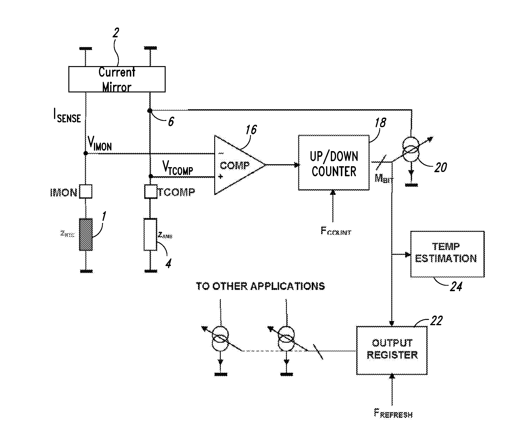
[0030]A novel compensation current generator according to one embodiment of the present disclosure is shown in FIG. 3. The current generator uses a single NTC thermistor 1 (in particular having a thermal compensation impedance ZNTC) in order to compensate on a pin IMON a temperature varying input current (ISENSE).

[0031]The voltage VIMON available on this pin is thus:

VIMON=ISENSE·ZAMB·[1−β(T−TAMB)]

wherein β represent the equivalent temperature coefficient of the impedance ZNTC of the thermistor 1 and ZAMB represents the equivalent resistance of the thermistor at reference room temperature.

[0032]The current generator includes a current mirror 2 configured to generate a replica current that is equal to the input current ISENSE, a resistor 4 having an impedance ZAMB that is equivalent to the impedance of the thermistor 1 at room temperature, and an adder 6 configured to provide, through another pin TCOMP a difference current given by the difference between the current ISENSE and a compe...


PUM

PropertyMeasurementUnit
input currentaaaaaaaaaa
resistanceaaaaaaaaaa
temperatureaaaaaaaaaa

Abstract

A current generator includes a thermistor configured to receive an input current, a reference resistor of a value substantially corresponding to a resistance of said thermistor at a reference temperature, a current mirror configured to generate a mirrored current proportional to said input current, a feedback circuit configured to generate an output compensation current proportional to a difference between voltages on said reference resistor and on said thermistor, and a first adder configured to force through said reference resistor a difference current between said mirrored replica current and said output compensation current.

Description

BACKGROUND[0001]1. Technical Field[0002]This disclosure relates to current generators and more particularly to a temperature compensation generator for a current to be compensated in function of the difference between current temperature and a reference temperature.[0003]2. Description of the Related Art[0004]Central processing units (CPUs) for personal computers (PCs), workstations and servers have very sophisticated supply control mechanisms. Their power supplies meet high precision specifications both in stand-by conditions as well as in conditions of load transients. It is known that, in order to reduce costs of the output filter of these systems, “voltage position” techniques, called also “droop function” or “load line regulation” based on programming the output resistance of the power supply converter, are often used.[0005]In order to prevent avoidable power dissipations and to sense the output current in a sufficiently refined and continuous manner, the parasitic conduction r...

Claims


Application Information

Patent Timeline
Patent Type & Authority Applications(United States)
IPC IPC(8): G05F1/46G01K7/00G01K7/16
CPCG05F3/262G05F3/245
Inventor ZAMBETTI, OSVALDO ENRICO
Owner STMICROELECTRONICS SRL
Why Eureka
Try Eureka