
Pump and actuator assembly for a self-inflating tire

Inactive Publication Date: 2012-06-28
THE GOODYEAR TIRE & RUBBER CO
View PDF3 Cites 24 Cited by
  • Summary
  • Abstract
  • Description
  • Claims
  • Application Information

AI Technical Summary

Benefits of technology

[0010]“Chafer” is a narrow strip of material placed around the outside of a tire bead to protect the cord plies from wearing and cutting against the rim and distribute the flexing above the rim.
[0024]“Sipe” means small slots molded into the tread elements of the tire that subdivide the tread surface and improve traction, sipes are generally narrow in width and close in the tires footprint as opposed to grooves that remain open in the tire's footprint.

Problems solved by technology

Accordingly, drivers must repeatedly act to maintain tire pressures or they will see reduced fuel economy, tire life and reduced vehicle braking and handling performance.
Such systems, however, remain dependant upon the driver taking remedial action when warned to re-inflate a tire to recommended pressure.

Method used


Image

  • Pump and actuator assembly for a self-inflating tire
  • Pump and actuator assembly for a self-inflating tire
  • Pump and actuator assembly for a self-inflating tire

Examples


Embodiment Construction

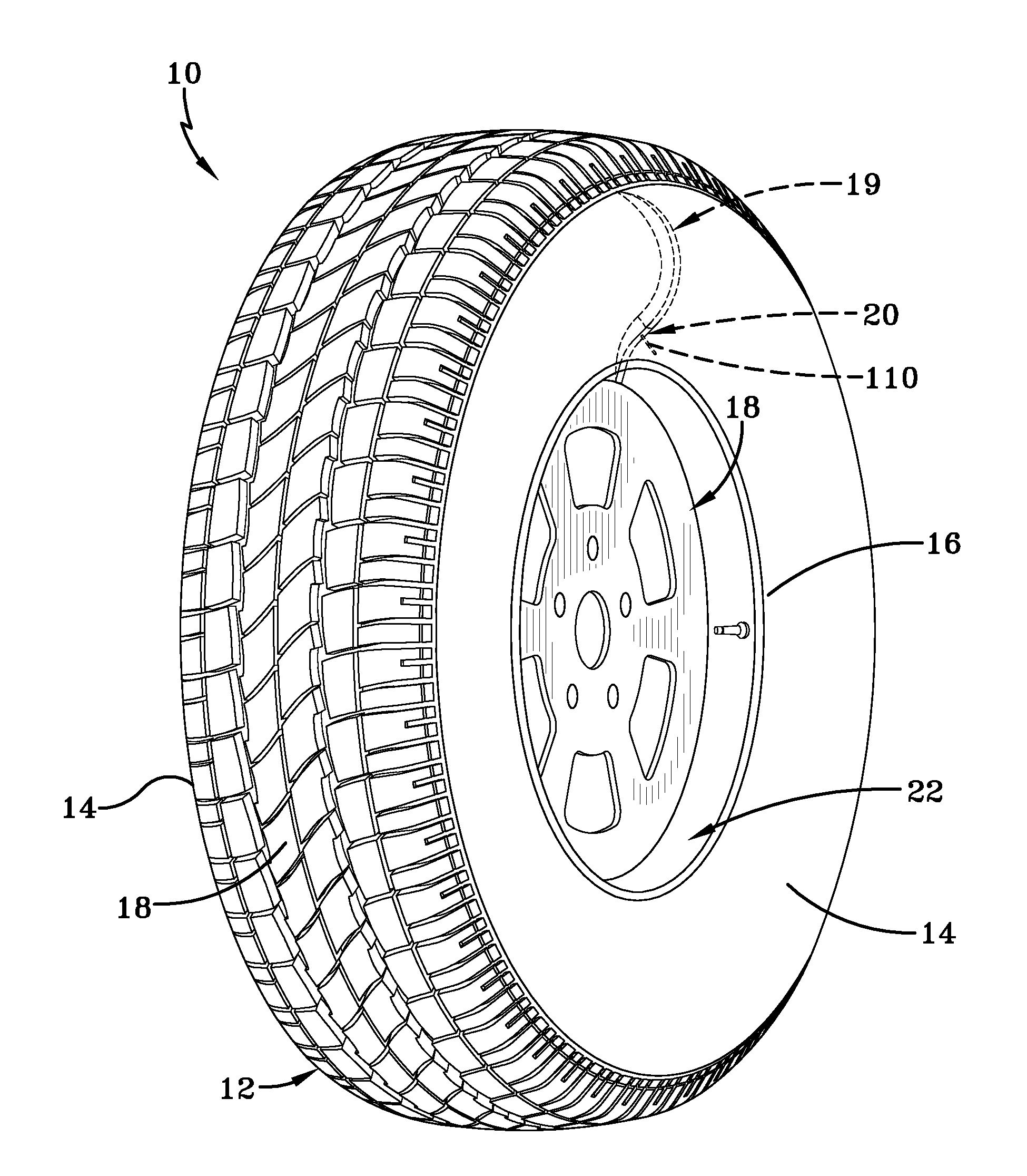
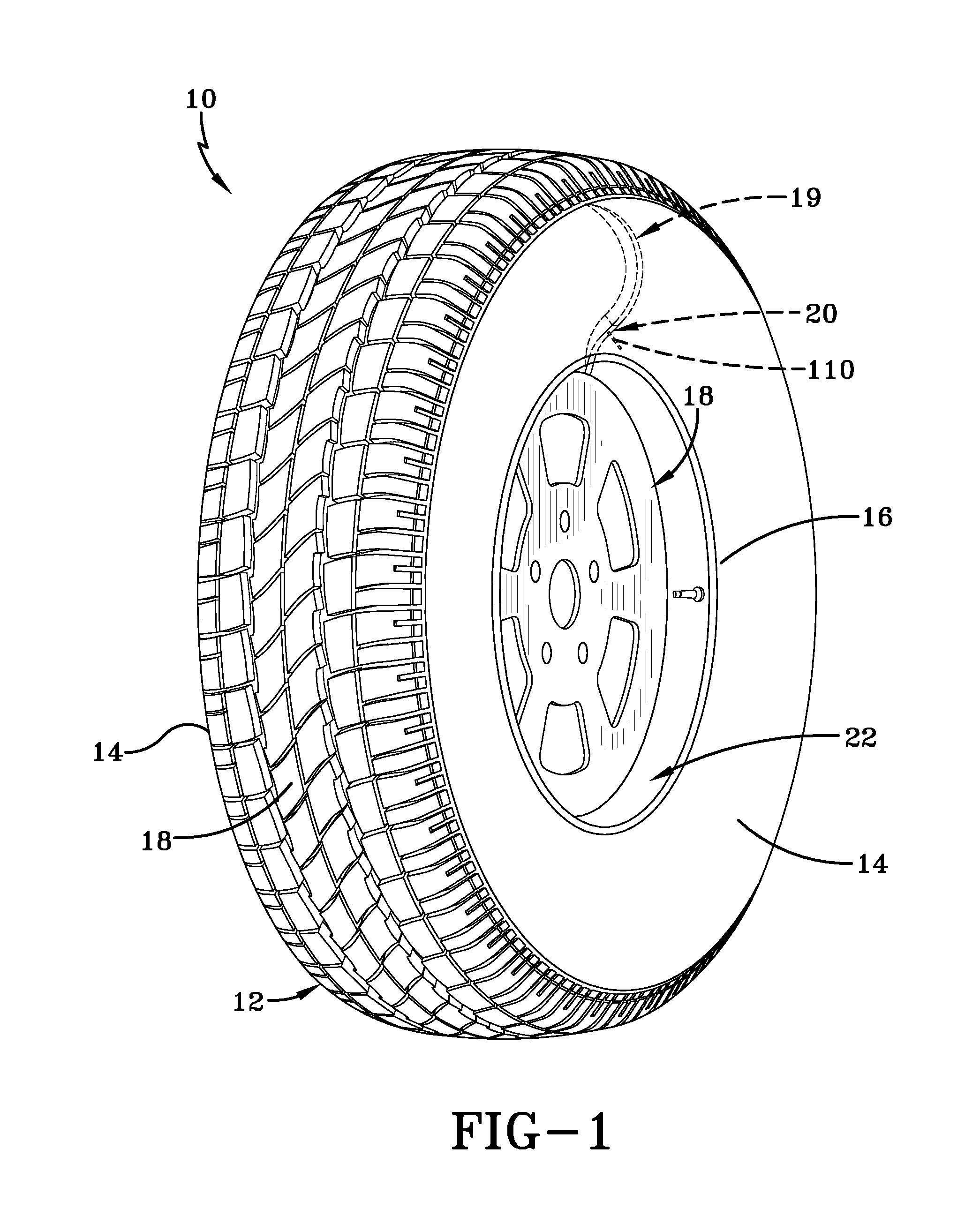
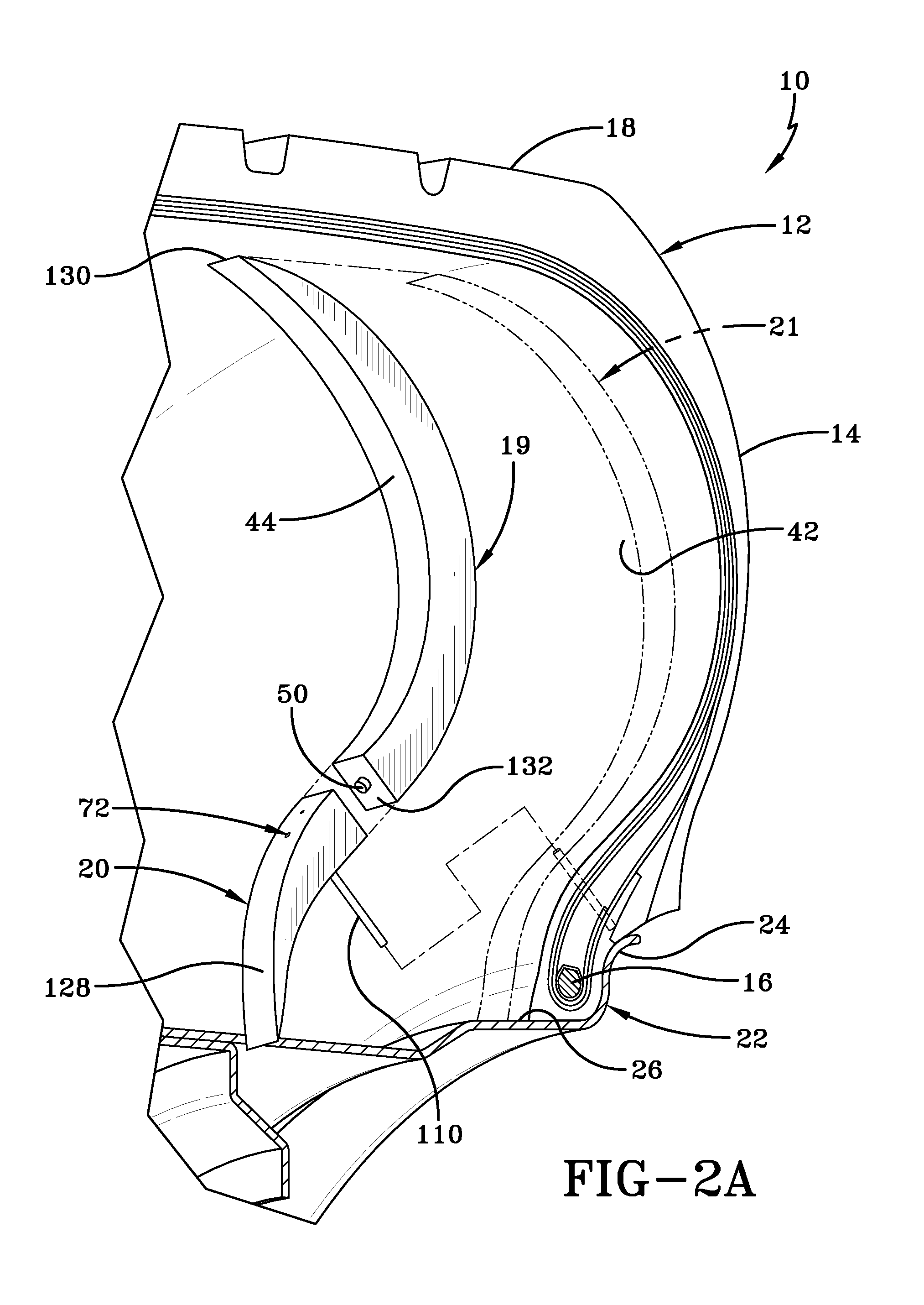
[0056]Referring to FIGS. 1, 2A, 2B, 3A, 3B, and 4, the subject Self-Inflating Tire System 10 is shown to include a tire carcass 12 of generally conventional construction having a pair of sidewalls 14, a pair of beads 16, and a tread 18. The tire 12 is configured to be self-inflating by inclusion of a pump assembly 20 and coupled compression actuator assembly 19, both of which being attached to the tire in a post-cure assembly procedure. As shown in FIG. 2A, the assembly 19 may be mounted to a sidewall 14 by application of adhesive as shown in phantom as adhesive area 21. The tire 12 mounts conventionally to a rim 22 having a tire mounting surface 26 and an outer rim flange 24 extending from surface 26. The tire 12 is further formed to provide an inner liner component 28 which defines and encloses an internal tire air cavity 30. Adhesive is applied to the sidewall region of the inner liner 28 as depicted by area 21. The tire 12 is formed to further provide a lower sidewall region 32 ...


PUM


Abstract

A self-inflating tire system includes a compression actuator assembly mounted to a tire carcass for compressing air for delivery to a tire cavity. The compression actuator assembly includes a hollow containment body formed from a resilient deformable material composition and containing a quantity of a non-compressible medium. The containment body is affixed to a relatively high flex-deformation region of the tire carcass and reciprocally transforms between a deformed state and a non-deformed state responsive to deformation and recovery of the tire high flex-deformation region in a rolling tire. Accordingly, the containment body in the deformed state displaces a pressurized displaced quantity of the non-compressible medium which generates a compression force for application to a volume of air delivered to the tire cavity. A pump assembly affixes to the tire carcass and includes valves for reciprocally opening and closing the inlet opening and the outlet opening of a compressor body synchronously with the cyclic transformation of the containment body.

Description

FIELD OF THE INVENTION[0001]The invention relates generally to self-inflating tires and, more specifically, to a self-inflating tire having an integrated air pumping system.BACKGROUND OF THE INVENTION[0002]Normal air diffusion reduces tire pressure over time. The natural state of tires is under inflated. Accordingly, drivers must repeatedly act to maintain tire pressures or they will see reduced fuel economy, tire life and reduced vehicle braking and handling performance. Tire Pressure Monitoring Systems have been proposed to warn drivers when tire pressure is significantly low. Such systems, however, remain dependant upon the driver taking remedial action when warned to re-inflate a tire to recommended pressure. It is a desirable, therefore, to incorporate a self-inflating feature within a tire that will self-inflate the tire.SUMMARY OF THE INVENTION[0003]In one aspect of the invention, a self-inflating tire system includes a compression actuator assembly mounted to a tire carcass ...

Claims


Application Information

Patent Timeline
IPC IPC(8): B60C29/04
CPCB60C23/12B60C23/121B60C23/135B60C23/10B60C29/04B60S5/04
Inventor HINQUE, DANIEL PAUL LUC MARIECOLLETTE, JEAN JOSEPH VICTORBORMANN, RENE LOUISRUSSO, MASSIMO DI GIACOMOBONNET, GILLES
Owner THE GOODYEAR TIRE & RUBBER CO
Learn More