
Trough shaped fresnel reflector solar concentrator

a solar concentrator and fresnel reflector technology, applied in solar heat systems, pv power plants, light and heating equipment, etc., can solve the problems of loss of reflectors and subsequent lower efficiency, and achieve the effect of convenient and inexpensive manufacture, less expensive, and improved efficiency

Inactive Publication Date: 2012-06-28
CITRON JEFFREY MICHAEL
View PDF3 Cites 41 Cited by
  • Summary
  • Abstract
  • Description
  • Claims
  • Application Information

AI Technical Summary

Benefits of technology

[0007]One advantage of the present invention compared to curved trough concentrators is that its' flat linear structure is easily amenable to inexpensive manufacture by being stamped from metallic materials of various gauges. Also it can easily be installed in a protective housing to shield it from environmental factors such as wind loading and hail. If such a housing is provided with a glazing the resulting collector will have thermal insulation properties when built as a thermal collector, properties that most parabolic concentrators lack. In such a configuration commonly available and less expensive tracking mechanisms may be used compared to those required with parabolic troughs.
[0008]Compared to flat sided V shaped troughs the present concentrator will have an advantage in efficiency because no solar ray is subject to more than 2 reflections before reaching the receiver and most rays are only subject to one reflection. Flat sided V shaped troughs of higher concentration ratios require multiple reflections of some rays causing loses to the reflector and subsequent lower efficiency. Another advantage of the present invention compared to flat sided V trough concentrators and compound parabolic concentrators in higher concentration ratios, is that the present invention is amenable to being made with wide underlying trough angles thus allowing for a concentrator of relatively high concentration ratio that is not excessively tall.

Problems solved by technology

Flat sided V shaped troughs of higher concentration ratios require multiple reflections of some rays causing loses to the reflector and subsequent lower efficiency.

Method used


Image

  • Trough shaped fresnel reflector solar concentrator
  • Trough shaped fresnel reflector solar concentrator
  • Trough shaped fresnel reflector solar concentrator

Examples


Embodiment Construction

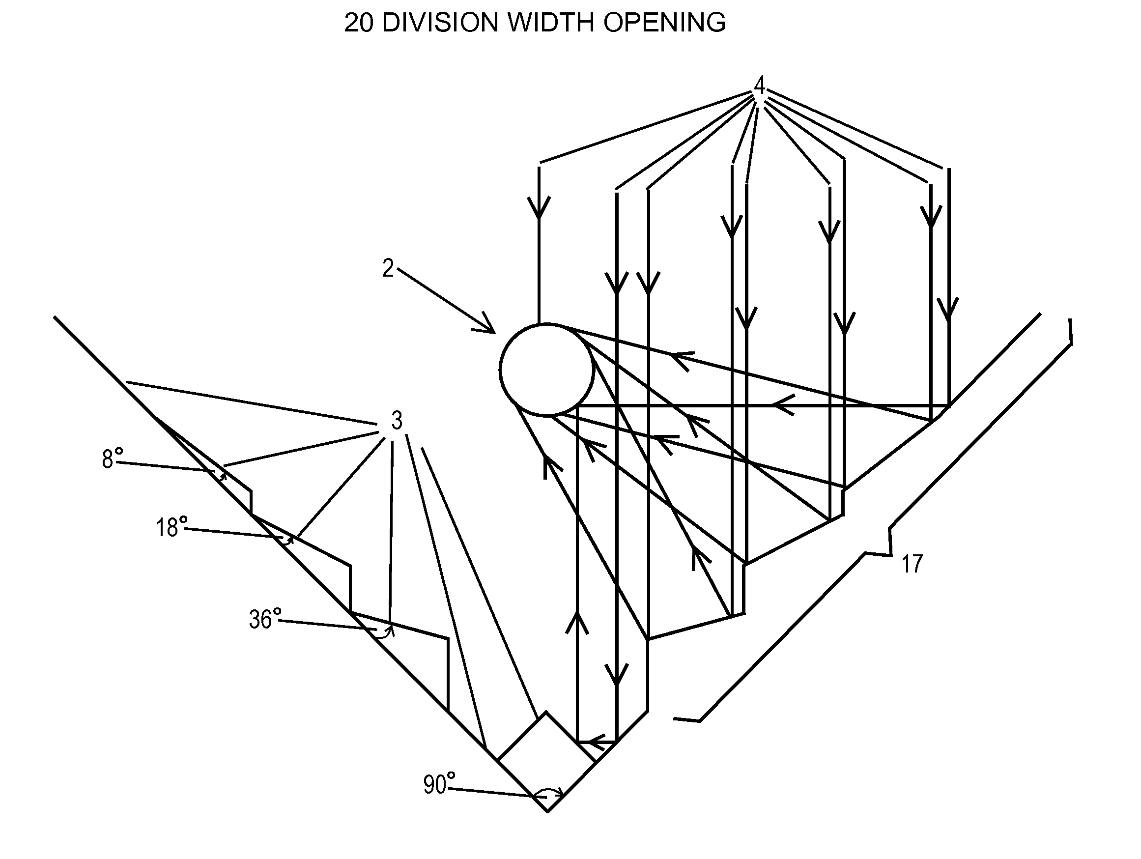
[0016]FIGS. 1a, b and c are crossectional representations of the basic concept of the present invention designed to illustrate the theory and operation of the invention.

[0017]Referring in detail to FIG. 1a the bracket 1 encompasses the structural elements of the trough shaped Fresnel reflector concentrator of the present invention. It shows the basic V shape of the underlying trough design with the Fresnel steps 3 which have highly reflective surfaces on their inner surfaces facing the inside of the trough. These Fresnel reflector steps 3 reflect all the light entering the mouth or upper opening of the trough structure and parallel to its' central axis onto a smaller area within the structure which is the focal area of the Fresnel reflector thus concentrating the light into that area. This unique shape and structure is the substance of the present invention.

[0018]By putting a solar energy receiving element 2 in the focal area along the length of the trough one preferred embodiment o...


PUM


Abstract

The present invention is a Solar Concentrator composed of a generally V shaped trough of reflective Fresnel steps. Said Fresnel reflective steps concentrate the sunlight entering the mouth of the V shaped trough and parallel to its' central axis into a central focal area. By disposing a solar energy receiving element at the central focal area of sunlight concentration a preferred embodiment as a concentrating solar energy collector is realized. Various types of solar energy receiving structures are shown that serve to convert the concentrated sunlight into other forms of useful energy to realize the preferred embodiment as a concentrating solar energy collector.

Description

[0001]This application is based on and claims the priority of this inventor's Provisional Patent Application No. 61 / 427,433, Filed Dec. 27, 2010.BACKGROUND OF THE INVENTION[0002]The present invention is in the field of solar concentrators. More particularly the present invention is shown in the configuration of a solar collector whose purpose is to concentrate solar energy and convert it into other useful forms of energy, although this is not intended to limit its' use to that purpose.[0003]Prior art trough shaped concentrators have either been of the curved, simple or compound parabolic shape, or flat sided V shaped troughs such as the present inventors' prior patent. Both these types of collectors have either cost or physical problems which are eliminated or improved upon by the present invention.[0004]Parabolic reflectors are complex shapes which are expensive to manufacture and require special and expensive support structures to maintain their shape in the outdoor environment of...

Claims


Application Information

Patent Timeline
IPC IPC(8): H01L31/058F24J2/04F24J2/10F24S23/70
CPCY02E10/52F24J2/1047F24J2/244F24J2/541F24J2002/1023H01L31/0547F24J2002/108F24J2002/241F24J2002/5441Y02E10/44Y02E10/47F24J2002/1061F24S10/74F24S23/80F24S30/425F24S2010/71F24S2023/834F24S2023/84F24S2023/872F24S2030/115
Inventor CITRON, JEFFREY MICHAEL
Owner CITRON JEFFREY MICHAEL
Learn More