Automated cabling layout systems and methods

a cabling layout and automatic technology, applied in the field of automatic cabling layout systems and methods, can solve the problems of conflicting rules and rule violations, difficult to plan cabling layouts, and time-consuming current planning processes for planning cabling layouts

Active Publication Date: 2012-06-21
FLUOR TECH CORP
View PDF1 Cites 21 Cited by
  • Summary
  • Abstract
  • Description
  • Claims
  • Application Information

AI Technical Summary

Benefits of technology

[0021]Various objects, features, aspects and advantages of the inventive subject matter will become more apparent from the following detailed description of preferred embodiments, along with the accompanying drawing figures in which like numerals represent like components.

Problems solved by technology

Planning a cabling layout can be a very complex and difficult task, especially for large construction projects.
Current planning processes for planning cabling layouts are time consuming.
At this point, the engineer will often encounter conflicts and rule violations, due to the interdependency of many different parameters and constraints.
In addition to being time consuming, current methods and systems for planning cabling layouts fail to account for the constantly changing nature of large construction projects.
Unfortunately, a design change in one area the construction project can affect the cabling layout in a distant area of the project.
Some effort has been directed toward alleviating these issues but such efforts still fall short.
However, such algorithms fail to take into account past experiences of laying out cable runs.
Although the above set of references advance cabling routing technologies to some degree, they also fail to address the need for incorporating previous experiences into automated cabling layout design processes.
Moreover, the above references fail to provide a recommendation engine for providing recommendations on tray sizes (either standard or custom sizes), number of lanes per route, and cable assignment to lanes.

Method used


Image

  • Automated cabling layout systems and methods
  • Automated cabling layout systems and methods
  • Automated cabling layout systems and methods

Examples


Embodiment Construction

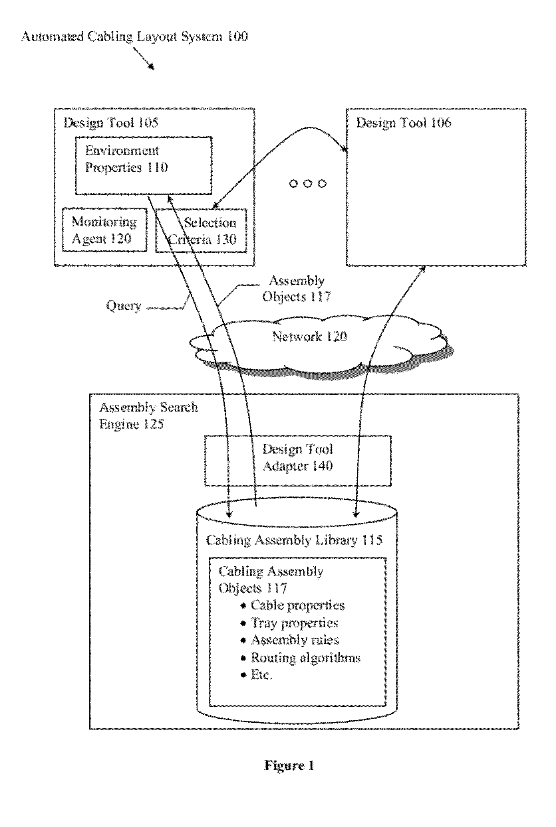
[0029]It should be noted that while the following description is drawn to a computer / server-based cabling layout systems, various alternative configurations are also deemed suitable and may employ various computing devices including servers, interfaces, systems, databases, engines, controllers, or other types of computing devices operating individually or collectively. One should appreciate the computing devices comprise a processor configured to execute software instructions stored on a tangible, non-transitory computer readable storage medium (e.g., hard drive, solid state drive, RAM, flash, ROM, etc.). The software instructions preferably configure the computing device to provide the roles, responsibilities, or other functionality as discussed below with respect to the disclose apparatus. In especially preferred embodiments, the various servers, systems, databases, or interfaces exchange data using standardized protocols or algorithms, possibly based on HTTP, HTTPS, AES, public-p...


PUM


Abstract

Automated cabling layout systems and methods are presented. A cabling assembly library stores multiple generic, design-tool agnostic cabling assembly objects representing cabling layout objects (e.g., cables, trays, mounts, conduits, etc.). The cabling assembly objects further include design rules governing the conditions of use of the cabling assembly object. Design engineers or designers can query the library to identify appropriate cabling assembly objects that would be appropriate for using within a modeled physical environment. One or more matching cabling assembly objects can be converted to an appropriate format for a design tool and instantiated into the modeled environment. The design tool can create modeled cabling layouts from the instantiated assemblies according to the design rules of the corresponding cabling assembly objects.

Description

[0001]This application claims the benefit of priority to U.S. Patent Application Ser. No. 61 / 423,199 filed on Dec. 15, 2010, which is incorporated by reference in its entirety.FIELD OF THE INVENTION[0002]The field of the invention is computer aided design technologies, specifically, systems and methods for planning cabling layouts.BACKGROUND[0003]When designing a construction project, design engineers are required to plan a layout for installing various cables, such as power lines and communication lines (e.g., Ethernet cable, fiber optics cable, telephone cable, etc). Planning a cabling layout can be a very complex and difficult task, especially for large construction projects. The design engineer's responsibilities include: defining cable routes, selecting and / or designing hardware (e.g., trays, fasteners, electrical panels), determining the number of lanes per route, and assigning cables to lanes, among many other things. The design engineer's principle objective is to plan a cab...

Claims


Application Information

Patent Timeline
Patent Type & Authority Applications(United States)
IPC IPC(8): G06F17/50G06N5/02
CPCG06F17/5004G06F2217/36G06F17/509H02G3/28H02G3/00H02G3/0456G06F17/5095G06F30/13G06F30/15G06F30/18G06F2113/16
Inventor LOGATOC, MICHAEL I.
Owner FLUOR TECH CORP
Why Eureka
Try Eureka