
Devices and method for determining and monitoring a cardiac status of a patient by using plvdt or plvst parameters

a technology of cardiac status and parameters, applied in the field of implantable medical devices, can solve problems such as compromising performance during systole, and achieve the effect of improving specificity and accurately and reliably determining the cardiac status of patients

Active Publication Date: 2012-06-21
ST JUDE MEDICAL
View PDF5 Cites 9 Cited by
  • Summary
  • Abstract
  • Description
  • Claims
  • Application Information

AI Technical Summary

Benefits of technology

[0009]According to another object of the present invention, there is provided an improved medical device and method for accurately and reliably determining a cardiac status of a patient.
[0010]According to a further object of the present invention, there is provided a medical device and method capable of determining a cardiac status of patient with an improved specificity.
[0019]According to an embodiment of the present invention, a prognosis based on a present rate of change of PLVDT (or PLVST) is determined. For example, the present rate of change is extrapolated and a future point of time when a lower or higher limit of a predetermined range of the PLVDT (or PLVST), which may be patient specific e.g. within 55%-65% (or 35%-45% for PLVST) at a specific activity level and / or heart rate or a range of activity levels and / or heart rates, is crossed can be calculated. The patient may, for example, be alerted that a worsening of the heart failure status can be expected within a certain period of time. Thus, this gives the patient time to take measures or precautions to avoid the potential event.

Problems solved by technology

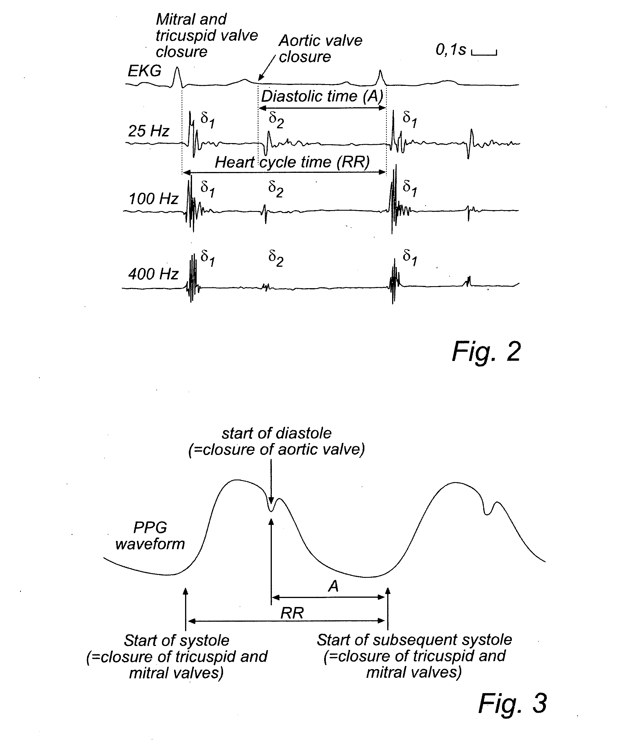
If the diastolic phase is disturbed or shortened in time, the performance during systole is compromised.

Method used


Image

  • Devices and method for determining and monitoring a cardiac status of a patient by using plvdt or plvst parameters
  • Devices and method for determining and monitoring a cardiac status of a patient by using plvdt or plvst parameters
  • Devices and method for determining and monitoring a cardiac status of a patient by using plvdt or plvst parameters

Examples


Embodiment Construction

[0034]The following is a description of exemplifying embodiments in accordance with the present invention. This description is not to be taken in limiting sense, but is made merely for the purposes of describing the general principles of the invention. It is to be understood that other embodiments may be utilized and structural and logical changes may be made without departing from the scope of the present invention. Thus, even though particular types of implantable medical devices such as heart stimulators will be described, e.g. biventricular pacemakers, the invention is also applicable to other types of cardiac stimulators such as dual chamber stimulators, implantable cardioverter defibrillators (ICDs), etc.

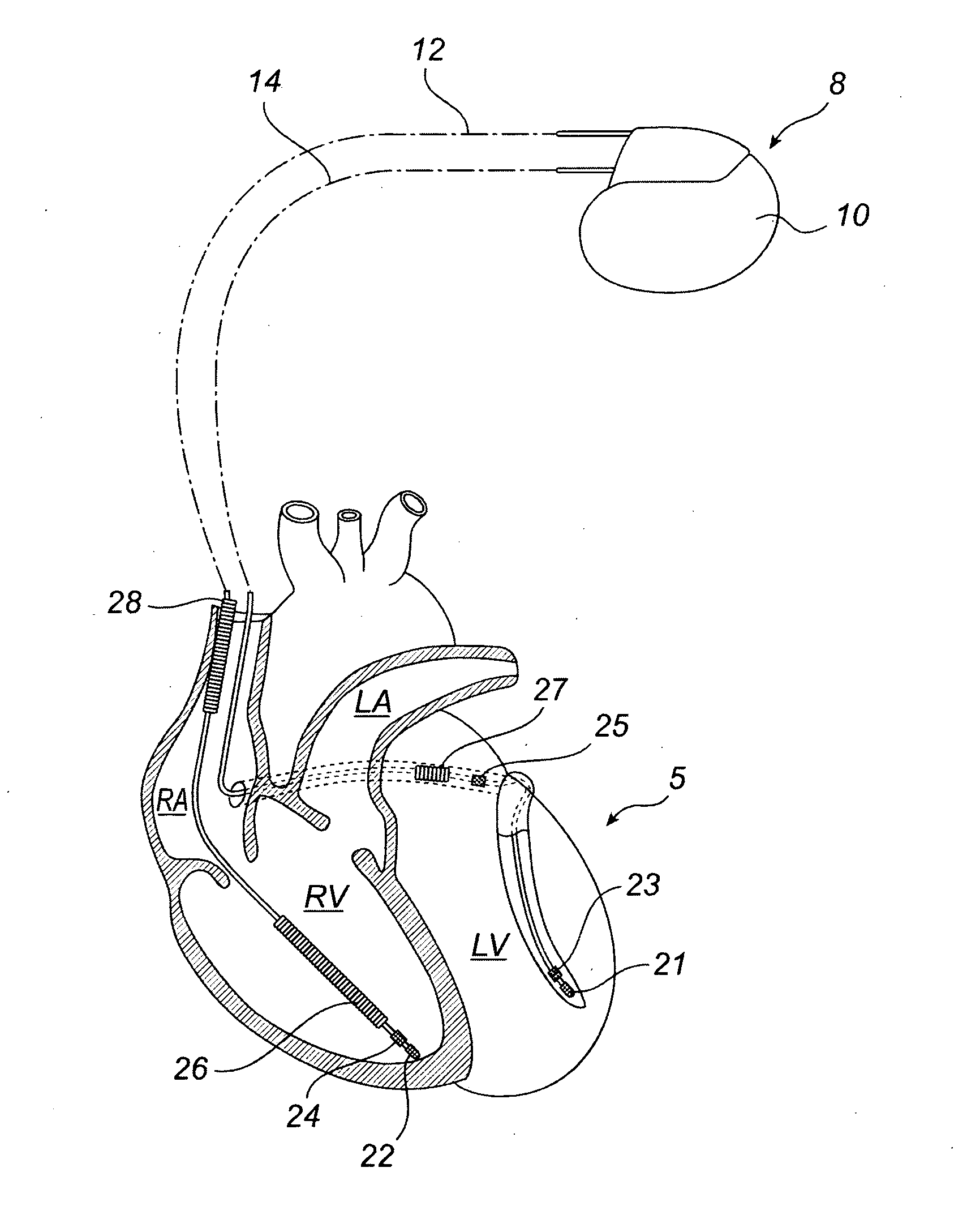
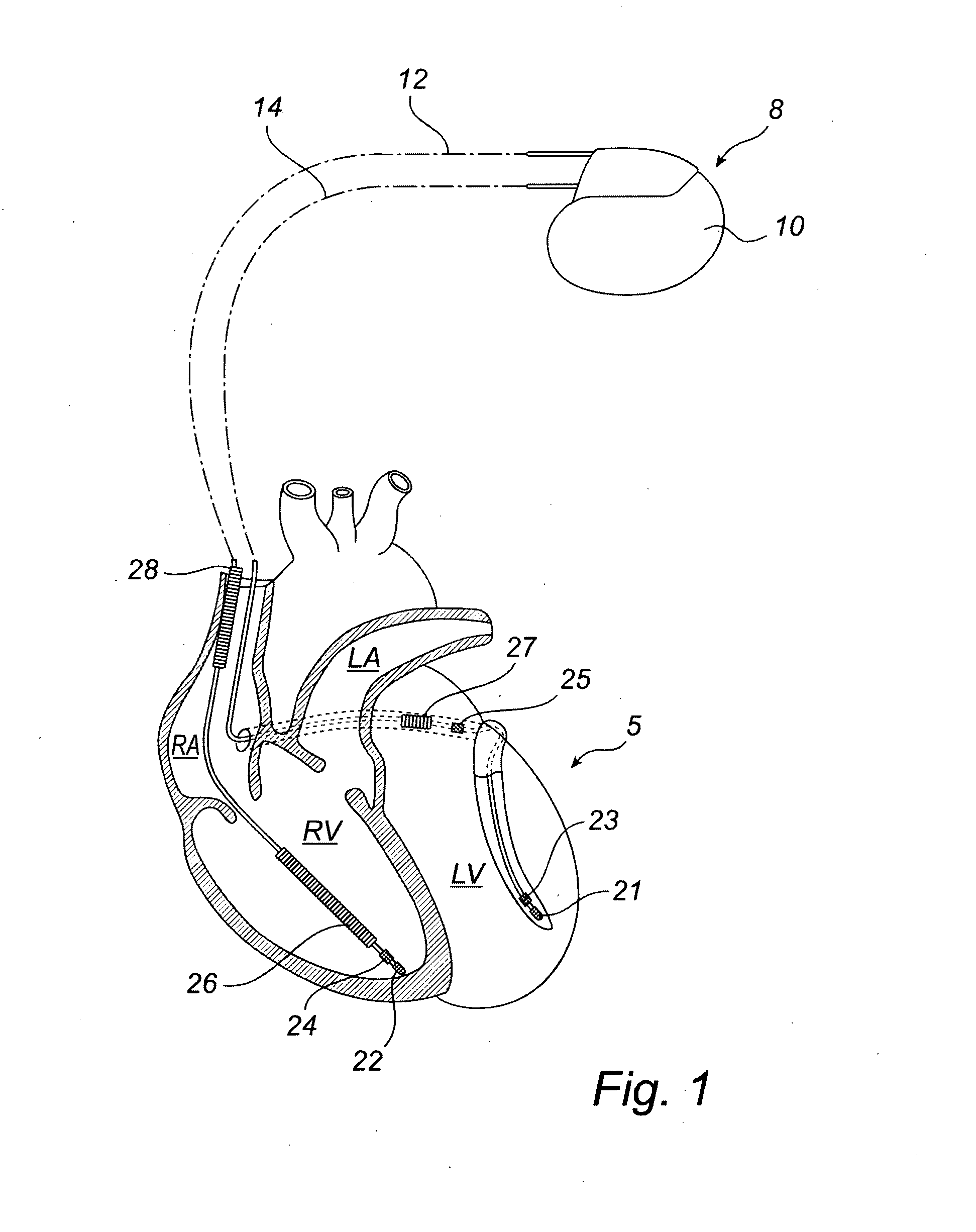
[0035]Turning now to FIG. 1, which is a simplified schematic view of one embodiment of an implantable medical device (“IMD”) 8 according to the present invention. IMD 8 has a hermetically sealed and biologically inert case 10. In this embodiment, IMD 8 is a pacemaker which is ...


PUM


Abstract

The present invention relates to an improved medical device and method for accurately and reliably determining a cardiac status of a patient. An implantable medical device, IMD, comprises a sensor arrangement adapted to sense signals related to mechanical activity of the heart and an activity level sensor arrangement adapted to sense an activity level of the patient. Further, the IMD calculates a percentage of left ventricular diastolic time (PLVDT) for a cardiac cycle corresponding to a relation between a diastolic time interval and a cardiac cycle time interval using the determined systolic and diastolic time intervals or a percentage of left ventricular systolic time (PLVST) for a cardiac cycle corresponding to a relation between a systolic interval time interval and a cardiac cycle time interval. A cardiac status is determined based on the calculated PLVDT (or PLVST) and on an activity level of the patient.

Description

TECHNICAL FIELD[0001]The present invention generally relates to implantable medical devices, such as pacemakers, and, in particular, to techniques for determining and monitoring a cardiac status of a patient.BACKGROUND OF THE INVENTION[0002]The cardiac cycle has two phases; diastole and systole. During the systolic phase, the heart ejects blood through a pumping action requiring energy. During the diastolic phase, the heart repolarizes electrically, relaxes mechanically and is refilled with blood. In addition, the oxygen needed for the heart to perform its systolic activity is delivered to the heart during diastole. If the diastolic phase is disturbed or shortened in time, the performance during systole is compromised.[0003]In “Diastolic time—frequency relation in the stress echo lab: filling timing and flow at different heart rates”, by Bombardini T. et al., Cardiovascular Ultrasound, 2008 Apr. 21; 6:15, the diastolic and systolic time intervals were studied in normal persons, i.e....

Claims


Application Information

Patent Timeline
IPC IPC(8): A61B5/0402A61B5/0215A61B5/02A61B5/283A61B5/349
CPCA61B5/0452A61B5/1118A61B5/02A61N1/3627A61B5/6846A61B5/349A61B5/283A61B5/0215A61B5/02416A61B5/1102A61B5/7275A61B5/7278A61B7/023
Inventor JARVERUD, KARINBJORLING, ANDERSSNELL, JAY
Owner ST JUDE MEDICAL
Learn More