
Ophthalmic instrument for the measurement of ocular refraction and visual simulation, and associated methods of measurement of ocular refraction, simulation of ophthalmic elements, visual simulation and for obtaining optical parameters

a technology which is applied in the field of ophthalmic instruments for the visual simulation, and associated methods of measurement of ocular refraction, visual simulation and for obtaining optical parameters, can solve the problems of lack of method that is capable of estimating sharpness or sensibility, and lack of ability to correctly focus on objects located at different distances

Active Publication Date: 2012-06-21
UNIVERSITY OF MURCIA
View PDF5 Cites 5 Cited by
  • Summary
  • Abstract
  • Description
  • Claims
  • Application Information

AI Technical Summary

Benefits of technology

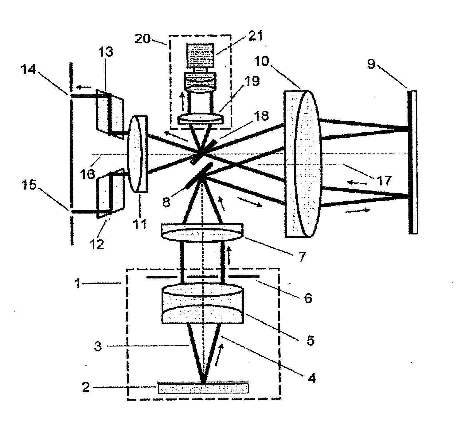
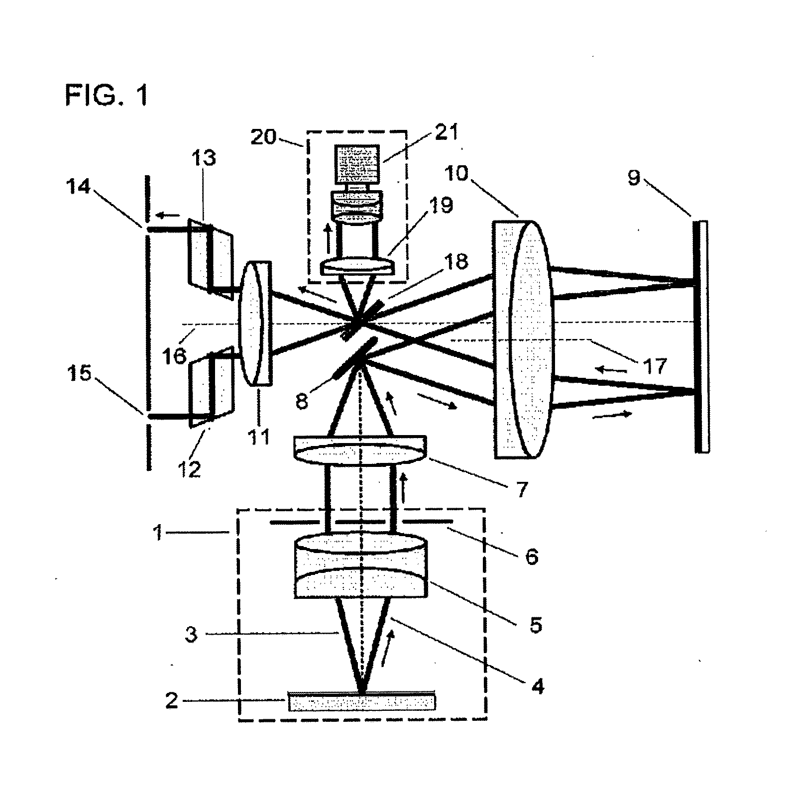
[0038]The instrument that implements the present invention fosters a practical, compact implementation with a relatively small number of elements. The use of lenses aligned along different optical axes enables the formation of two telescopic system that optically conjugate three separate planes by means of the utilization of only three lenses or, with the same result, spherical mirrors.
[0039]The instrument enables the modification of the aberrations through which the subject perceives a series of visual stimuli by means of a single aberration generator or phase modulator. This is controlled digitally from a computer. In this way the different corrections for the compensation of myopia, hyperopia, astigmatism and presbyopia or tired eyes are generated without the need to incorporate new elements into the system, and without the manipulation of moving parts. The phase modulator not only enables obtaining corrections for the different ametropias based on the modification of the blurring or astigmatism, but also any aberration phase profile of the highest order can be incorporated and the vision stimulated through it.
[0042]With the same effect although more complex and expensive, the system can incorporate two phase modulator elements instead of one.
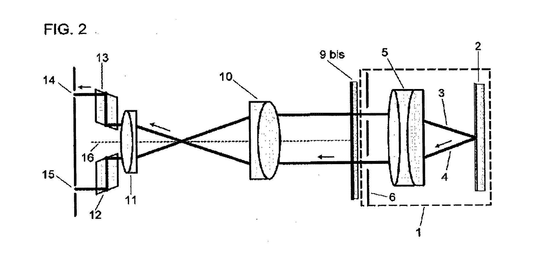
[0046]In an alternative embodiment of the instrument, one of the telescopic systems is removed, leaving only the plane of the input pupils and that of the output pupils as conjugated planes in the phoropter. In this way a much more compact instrument is obtained without the loss of features, for which it is necessary to use a phase modulator that operates in transmission, or equally, a beam splitter placed immediately in front of the phase modulator in reflection to correctly guide the light issuing from the subsystem for presentation of visual stimuli towards the subject.
[0047]The instrument object of the present invention can function in monocular mode, just as classic phoropters operate, simply by occluding one of the eyes. For this there is no need to use additional elements in the system or moving parts, but rather the phase modulator device can generate this effect. In an alternative embodiment of the instrument, the function of occlusion is obtained by means of a matrix of micro-mirrors placed in front of the subsystem for presentation of visual stimuli.

Problems solved by technology

It also occurs that the eye undergoes a series of changes due to age related developments, which result in a loss of the ability to correctly focus on objects located at different distances.
An issue that is inseparably linked to the measurement of ocular refraction is the available visual corrections.
However, it is now known that the refraction does not provide an objective measurement of the optical quality of the eye in an absolute sense.
Although optical quality is strongly linked to the quality of vision, there are no methods that are capable of estimating the sharpness or sensibility to contrast of a subject based on the values of the different optical parameters that characterize the eyes.
In these instruments the measurement of astigmatism is not obtained by means of variable strength lenses, and so for this ametropia it is still necessary to recur to the previous methods of mechanically interchanging and rotating the lenses.
In current state of the art there is clearly an enormous breach between modern means of correction of ametropic refractions, and of optical aberrations in general, with the measurement of the refraction or the subjective quality of vision.
However, as has previously been made manifest, the capacity and operation of current phoropters is quite removed from providing the necessary features for evaluating the vision of the patents, on the one side in a entirely digital manner, and on the other by incorporating the possibility of seeing through the phase profiles, or correction, beyond blurring and astigmatism, which can limit in a substantial manner the development of new corrections systems.

Method used


Image

  • Ophthalmic instrument for the measurement of ocular refraction and visual simulation, and associated methods of measurement of ocular refraction, simulation of ophthalmic elements, visual simulation and for obtaining optical parameters
  • Ophthalmic instrument for the measurement of ocular refraction and visual simulation, and associated methods of measurement of ocular refraction, simulation of ophthalmic elements, visual simulation and for obtaining optical parameters
  • Ophthalmic instrument for the measurement of ocular refraction and visual simulation, and associated methods of measurement of ocular refraction, simulation of ophthalmic elements, visual simulation and for obtaining optical parameters

Examples


Embodiment Construction

[0092]The invention disclosed consists in a method that enables obtaining the refraction of the subject in a binocular manner and the electro-optic instrument that implements it in the form of a phoropter. The method likewise enables the simulation of the most adequate correction for a previously detected ametropia, as well as any other ophthalmic element or visual condition in general.

[0093]The basic parts for the practical implementation of the instrument or phoropter that enables the object method of this invention is shown in a schematic way in FIG. 1. The system of FIG. 1 incorporates a subsystem for presentation of visual stimuli (1). Said subsystem (1) consists, in the first place, of a screen or micro-screen (2) where the scenes or images (25) to be presented to the subject are shown (an example of image (25) can be seen in FIG. 6). Screen (2) is controlled by a computer, from where images (25) are generated and programmed. Subsystem for presentation of visual stimuli (1) li...


PUM


Abstract

An ophthalmic instrument for measurement of ocular refraction and visual simulation and a method of measurement obtaining the ocular refraction in a binocular manner, which incorporates a digitally controlled phase modulator for generating best ophthalmic correction in each subject. The instrument enables measuring refraction, not only associated with blurring and astigmatism, but also optical aberration of any order. The phoropter can simulate vision by any phase profile, including those of a diffractive or discontinuous type. The instrument also incorporates a subsystem for presentation of stimuli that produces stereoscopic vision of the same, enabling the subject to enjoy a three dimensional perception during the process, and two output pupils. The instrument, by its electro-optical features, enables simulation of vision as it would be modified after submitting an eye to different surgical techniques, such as refractive surgery or interocular lens implantation.

Description

FIELD OF THE INVENTION[0001]The present invention refers to an instrument for the measurement of advanced ocular refraction, preferentially in a binocular manner, and of visual simulation. Thus the apparatus pertains to the family of instruments known as phoropters. In these instruments a finite collection of lenses can be interchanged in a simultaneous manner to the vision on the part of the patient of visual stimuli or tests. In this way it can be discerned which optical corrections (limited to combinations of blurring and astigmatism) provide the best visual perception for each subject.[0002]The present invention also refers to a method for the measurement the ocular refraction of the eyes, to a method of simulation of ophthalmic elements, to methods of obtaining optical parameters and to methods of simulation of vision.[0003]The object the present invention does not employ moveable parts associated with the changing of lenses, but rather pertains to those systems in which the ef...

Claims


Application Information

Patent Timeline
IPC IPC(8): A61B3/08
CPCA61B3/0025A61B3/1015A61B3/107A61B3/103A61B3/028
Inventor FERNANDEZ MARTINEZ, ENRIQUE J.PRIETO CORRALES, PEDROARTAL SORIANO, PABLO
Owner UNIVERSITY OF MURCIA
Learn More