
Gas burner

a burner and gas technology, applied in the direction of combustion process, combustion ignition, heating fuel, etc., can solve the problems of difficult to provide a burner, inability to maintain the air/gas mixture uniformly over all the outlet passages, etc., and achieve the effect of stable combustion

Active Publication Date: 2012-06-21
ELECTROLUX HOME PROD CORP NV
View PDF27 Cites 14 Cited by
  • Summary
  • Abstract
  • Description
  • Claims
  • Application Information

AI Technical Summary

Benefits of technology

The invention relates to a burner system that can ignite a gas/air mixture using a low power flame from a high power burner. This prevents incomplete combustion of the gas/air mixture from the high power burner and ensures a stable flame. The system also includes a spark plug for the low power burner to further enhance ignition. The flames from the low power burner help to stabilize the gas/air mixture released from the high power burner, especially at low power settings. This prevents incomplete combustion of the gas/air mixture from the high power burner and ensures a stable flame.

Problems solved by technology

The technical problem addressed in this patent text is to provide a gas burner that can operate within a wide power range, allowing for high and low power operations. This is achieved by improving the gas flow rate and maintaining uniform release of the air/gas-mixture over all the outlet passages in the flame crown of the burner.

Method used


Image

  • Gas burner
  • Gas burner
  • Gas burner

Examples


Embodiment Construction

[0033]Below, one embodiment of the present invention will be described with reference to the figures. In the figures, like parts are denoted by like reference numbers.

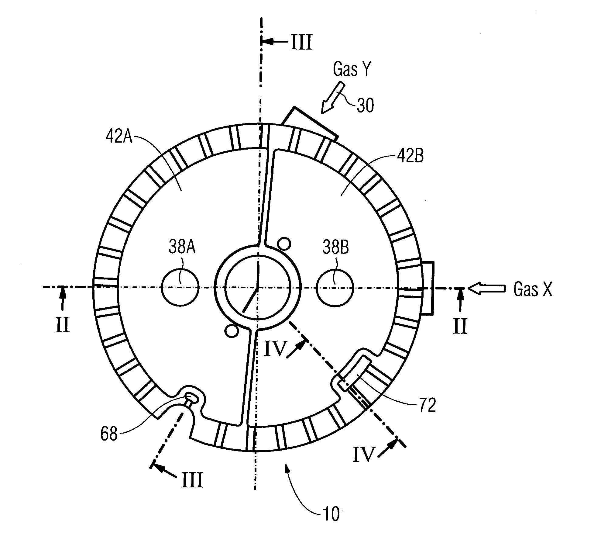
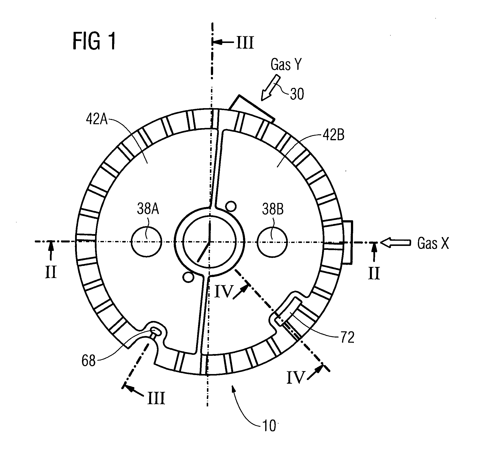
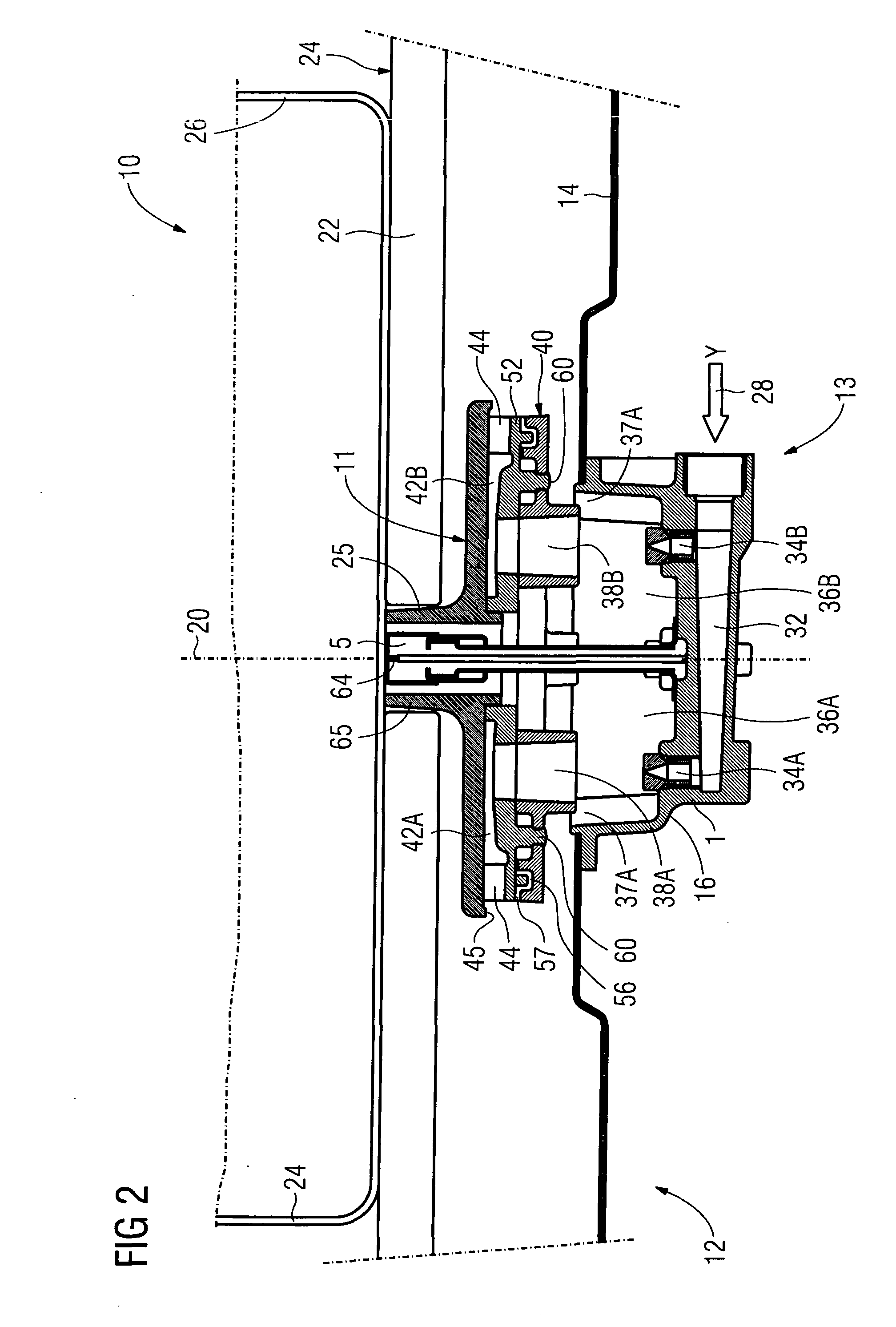
[0034]The gas burner 10 shown throughout the figures is one of a plurality of gas burners of a gas appliance 12 according to the invention. The gas burner 10 comprises a burner arrangement 13, which is received in a base plate 14 forming the top side of a cabinet of the gas appliance 12. The burner unit arrangement 13 is formed by a high power burner unit 16 and a low power burner 18, which are arranged around a common vertical axis 20. Moreover, the gas appliance 12 comprises a supporting structure 22 defining a flat, horizontally extending upper surface 24 for receiving a cooking recipient 26 thereon, as it is shown in FIG. 2.

[0035]The burner units 16 and 18 are supplied with a combustion gas by means of a main pipe (not shown in the figures), which branches to a first branch pipe 28 leading gas to the high power bur...


PUM


Abstract

The invention provides a gas burner (10) with a high power burner unit and a low power burner unit.

Description


Claims


Application Information

Patent Timeline
Owner ELECTROLUX HOME PROD CORP NV
Learn More