Method for operating flash memories on a bus

a bus and flash memory technology, applied in the field of flash memory operation, can solve the problems of inconvenient operation of the bus, inability to achieve the best efficiency of operating two flash memories, and the idle time of the bus

Active Publication Date: 2012-06-14
ETRON TECH INC
View PDF3 Cites 0 Cited by
  • Summary
  • Abstract
  • Description
  • Claims
  • Application Information

AI Technical Summary

Benefits of technology

The present invention describes how to operate flash memories connected to a computer network (also known as a bus). By following a specific order of operations, the system can make use of multiple flash memories simultaneously without compromising their performance or efficiency. This results in faster processing times and better overall data transmission over the network.

Problems solved by technology

The technical problem addressed in this patent relates to improving operational efficiency between multiple flash memories connected through a shared bus.

Method used


Image

  • Method for operating flash memories on a bus
  • Method for operating flash memories on a bus
  • Method for operating flash memories on a bus

Examples


Embodiment Construction

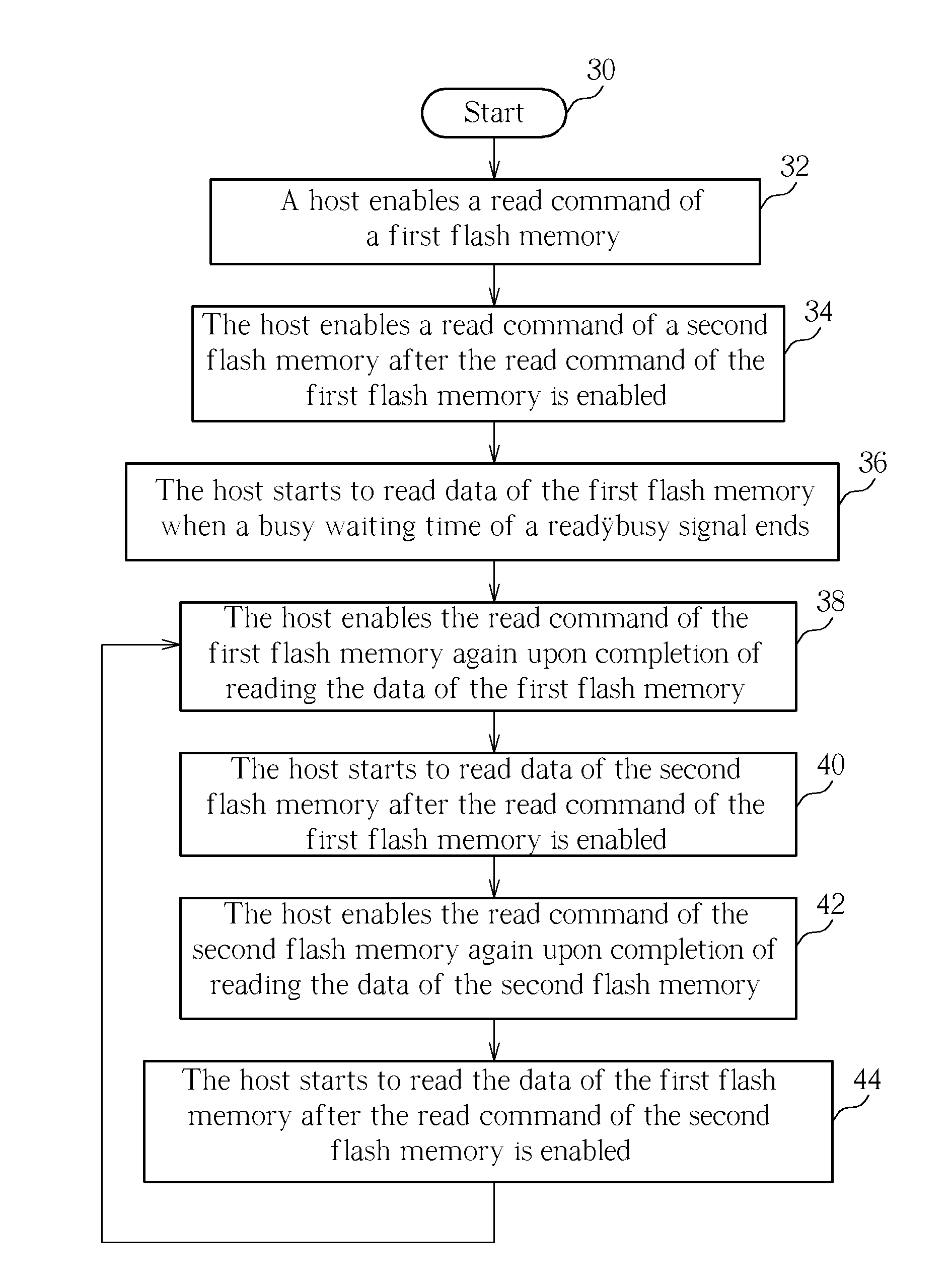
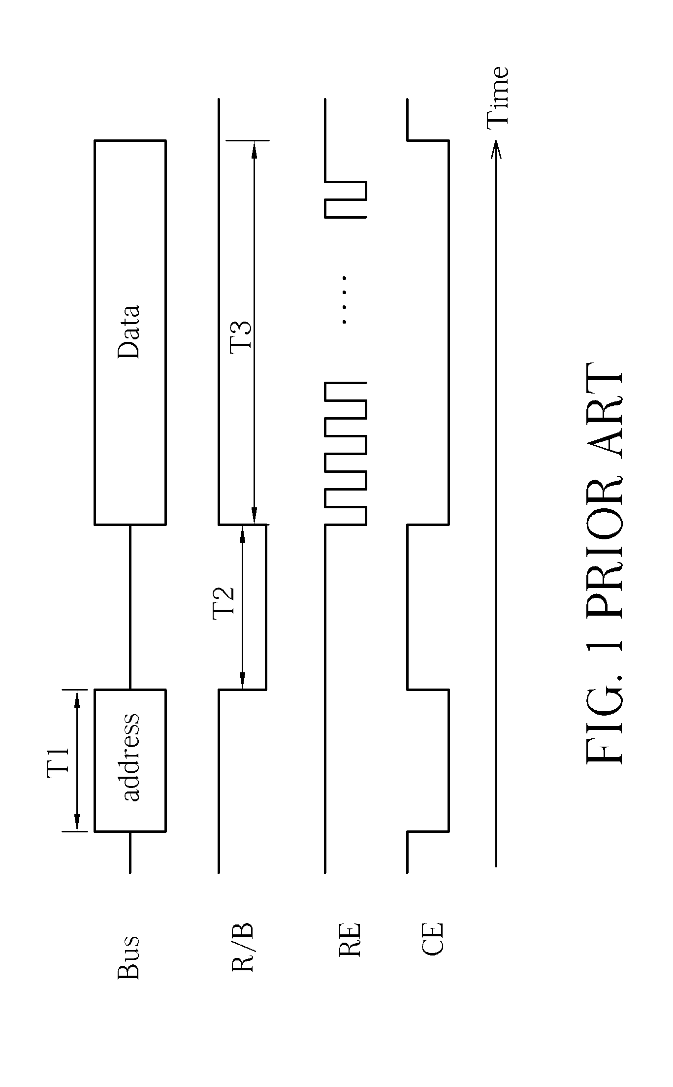
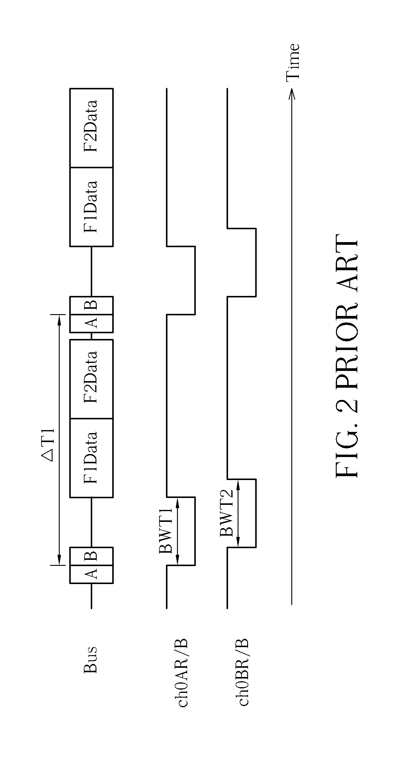
[0014]Please refer to FIG. 3 and FIG. 4. FIG. 3 is a flowchart illustrating a method for operating flash memories on a bus according to an embodiment, and FIG. 4 is a timing diagram of the method shown in FIG. 3. Detailed steps of the method shown in FIG. 3 are as follows:

[0015]Step 30: Start.

[0016]Step 32: A host enables a read command A of a first flash memory.

[0017]Step 34: The host enables a read command B of a second flash memory after the read command A of the first flash memory is enabled.

[0018]Step 36: The host starts to read data F1Data of the first flash memory when a busy waiting time BWT1 of a ready / busy signal ch0AR / B ends.

[0019]Step 38: The host enables the read command A of the first flash memory again upon completion of reading the data F1Data of the first flash memory.

[0020]Step 40: The host starts to read data F2Data of the second flash memory after the read command A of the first flash memory is enabled.

[0021]Step 42: The host enables the read command B of the sec...


PUM


Abstract

Enable a read command of a first flash memory. After the read command of the first flash memory is enabled, a ready/busy signal of the first flash memory enters a busy waiting time, and a read command of a second flash memory starts to be enabled. Start to read data of the first flash memory when the busy waiting time is over. Enable the read command of the first flash memory again upon completion of reading the data of the first flash memory. Start to read data of the second flash memory after the read command of the first flash memory is enabled again. And enable the read command of the second flash memory again upon completion of reading the data of the second flash.

Description


Claims


Application Information

Patent Timeline
Owner ETRON TECH INC
Why Eureka
Try Eureka