Method and System for Aligning Color Filter Array
a color filter and array technology, applied in the field of methods for aligning color filters, can solve the problems of abnormal display colors, crosstalk between image color channels, and alignment between color filters and light valves
- Summary
- Abstract
- Description
- Claims
- Application Information
AI Technical Summary
Problems solved by technology
Method used
Image
Examples
first embodiment
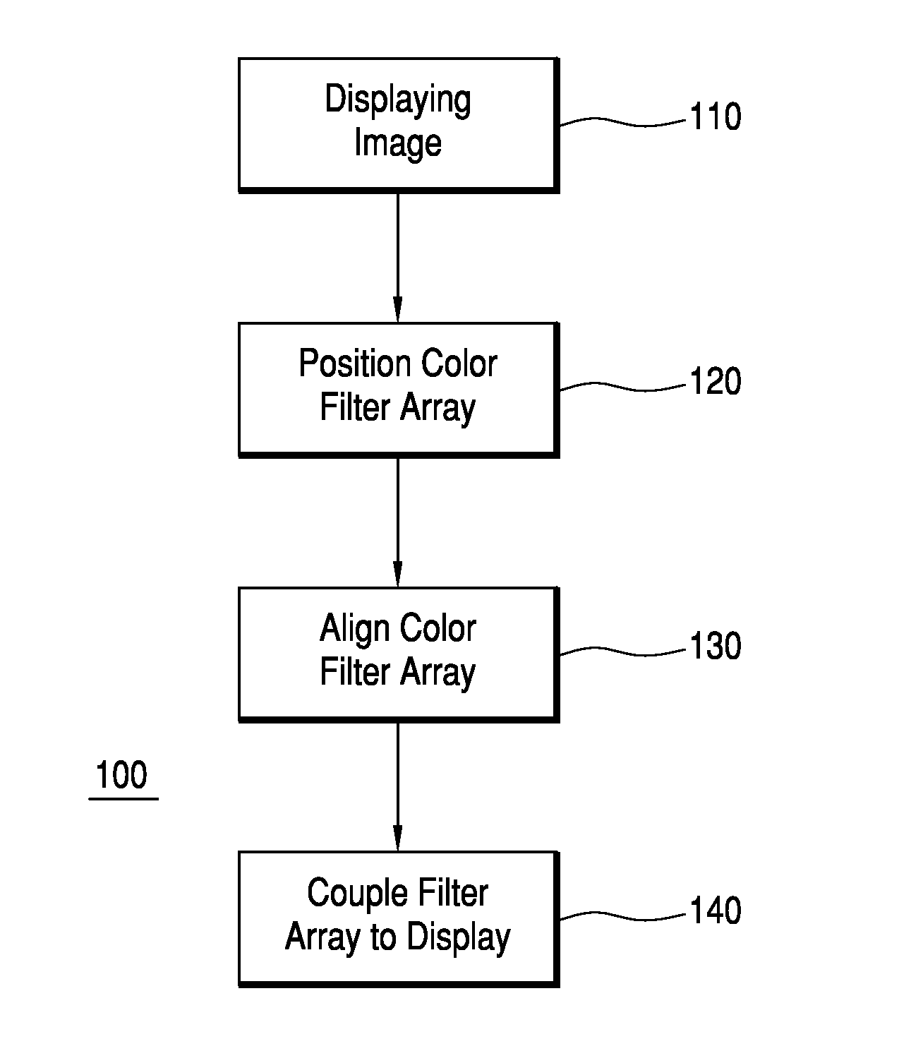
[0052]Turning to the drawings, FIG. 1 illustrates an example of a method of aligning a color filter array, according to a In the same or different embodiments, method 100 can be considered a method of aligning a color filter array with a display with backplane pixels which are not readily visible. Method 100 can also be considered a method of coupling a color filter array to a monochromatic display. Method 100 is merely exemplary and is not limited to the embodiments presented herein. Method 100 can be employed in many different embodiments or examples not specifically depicted or described herein.
[0053]In some embodiments, method 100 can comprise a procedure 110 of displaying an image on a display. The display can be any display in which a color filter array is to be coupled to the display. In some embodiments, the display is a monochromatic display. In other embodiments, the display is a chromatic display for which the color gamut is to be improved by additionally filtering the i...
second embodiment
[0074]Referring back to the figures, FIG. 22 illustrates an example of a support 2200 according to the invention. In many embodiments, support 2200 can be similar to support 300. In many embodiments, support 2200 comprises a body 2255 and filter opening 350. In the same or different embodiments, support 2200 further comprises cutout 2260. In many embodiments, cutout 2260 can provide similar functions to the cutouts of support 300. In the same or different embodiments, support 2200 further comprises holes 2299.
[0075]In some embodiments, procedure 120 (FIG. 1) of positioning the color filter array over the display can comprise a process 2310 (FIG. 23). FIG. 23 illustrates procedure 120 of positioning the color filter array, according to one embodiment.
[0076]In many embodiments, process 2310 can comprise providing a color filter array. In many embodiments, the color filter array can be similar to color filter array 1300 as described above. In some embodiments, process 2310 of providing...
PUM
 Abstract
Description
Claims
Application Information
 - R&D
- Intellectual Property
- Life Sciences
- Materials
- Tech Scout
- Unparalleled Data Quality
- Higher Quality Content
- 60% Fewer Hallucinations
Browse by: Latest US Patents, China's latest patents, Technical Efficacy Thesaurus, Application Domain, Technology Topic, Popular Technical Reports.
© 2025 PatSnap. All rights reserved.Legal|Privacy policy|Modern Slavery Act Transparency Statement|Sitemap|About US| Contact US: help@patsnap.com


