
Display systems incorporating fourier optics

Inactive Publication Date: 2012-06-07
BAE SYSTEMS PLC
View PDF7 Cites 77 Cited by
  • Summary
  • Abstract
  • Description
  • Claims
  • Application Information

AI Technical Summary

Benefits of technology

[0018]In a vehicular mounted head-up display system including such a signal processing system, the system can prevent or reduce the likelihood of errors in reading image information arising from diffraction angle induced errors.
[0021]The overall goal of head-up display and helmet mounted displays is to effectively interface the user with his surroundings, be it an aeroplane, a fellow crewmember in a search and rescue team, or a games console and video screen. In one embodiment, the present invention provides a head mounted device which, using simple optical devices, enables optical aberration issues arising from curved visors and the like to be overcome.

Problems solved by technology

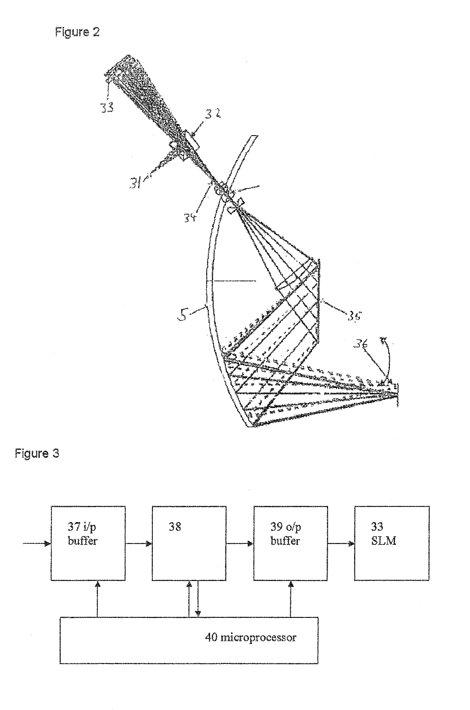
Ordinarily, for example in a helmet mounted display system, error correction is problematic when a single correction computer generated hologram is encoded in a spatial light modulator; the spatial light modulator is effectively at the stop of the system and accordingly a single correction cannot be implemented where aberrations such as field curvature are present.

Method used


Image

  • Display systems incorporating fourier optics
  • Display systems incorporating fourier optics
  • Display systems incorporating fourier optics

Examples


Embodiment Construction

[0026]There will now be described, by way of example only, the best mode contemplated by the inventor for carrying out the present invention. In the following description, numerous specific details are set out in order to provide a complete understanding to the present invention. It will be apparent to those skilled in the art that the present invention may be put into practice with variations of the specific.

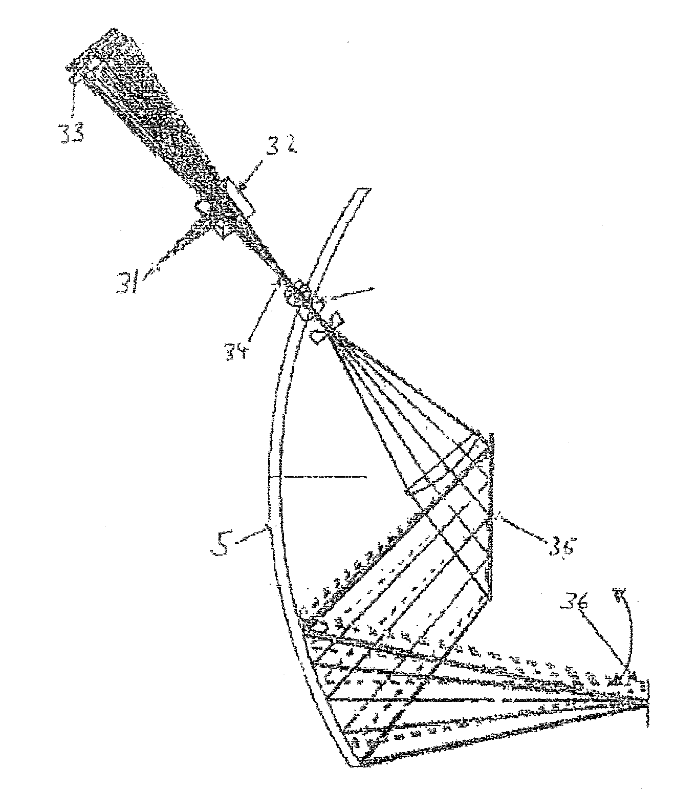
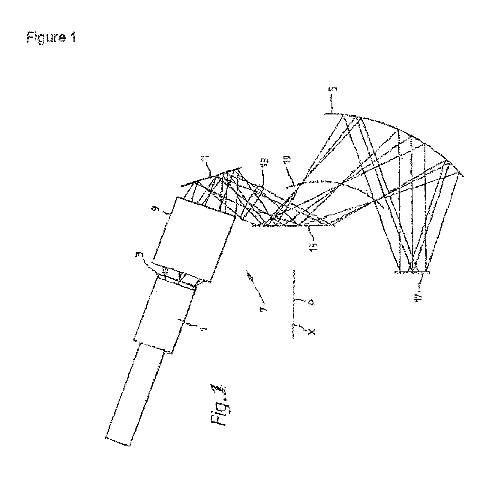
[0027]For simplicity, the present invention shall be generally described in relation to a head mounted display, although the same principles apply to other Fourier projections. Referring now to a FIG. 1, there is shown a prior art CRT head mounted display system. The display system is a binocular system and utilises two Fourier display systems (only one of which is shown in FIG. 1), one for each eye of a user of the system.

[0028]The display system for each eye comprises a miniature cathode ray tube (CRT) 1 comprising a screen 3. The image to be presented to the wearer of the he...


PUM


Abstract

A head up display signal processing system is disclosed. The system comprises an image projector for projecting an image onto a screen, the screen being partially reflective and partially transmissive. The system is operable to provide a separate optical element at a plurality of locations upon the screen, wherein each element comprises an optical phase representative of the location of the element upon the screen, such that the combination of optical elements is arranged to produce an optical hologram upon the screen.

Description

FIELD OF THE INVENTION[0001]The present invention relates to display systems incorporating Fourier optics and particularly, but not exclusively to head-up displays and head mounted displays as used by personnel in, for example, medicine, the emergency services, the military and virtual reality garners for providing hands-free visual data.BACKGROUND TO THE INVENTION[0002]A head-up display, or HUD, is any transparent display that presents data without requiring the user to look away from his or her usual viewpoint. The origin of the name sterns from the user, for example a pilot within a cockpit of an aircraft being able to view information with their head “up” and looking forward, instead of angled down looking at lower instruments situated within a cockpit. Although they were initially developed for military aviation, HUDs are now used in commercial aircraft, automobiles, and other applications.[0003]There are two types of head-up display: fixed head-up displays and helmet mounted d...

Claims


Application Information

Patent Timeline
IPC IPC(8): G03H1/08G03H1/22
CPCG02B27/0103G02B27/0172G02B2027/014G02B2027/013G02B2027/011
Inventor FREEMAN, JONATHAN PAUL
Owner BAE SYSTEMS PLC
Learn More