
Optical touch module capable of increasing light emitting angle of light emitting unit

a technology of optical touch and light emitting unit, which is applied in the direction of instruments, computing, electric digital data processing, etc., can solve the problems of unfavorable light distribution over the enlarged touch surface, incorrect positioning or touch failure, etc., and achieve the effect of increasing the light emitting angl

Active Publication Date: 2012-06-07
WISTRON CORP
View PDF7 Cites 8 Cited by
  • Summary
  • Abstract
  • Description
  • Claims
  • Application Information

AI Technical Summary

Benefits of technology

[0005]Compared with the light interruption method, in which the length of the reflective bar or the near-infrared light emitting bar needs to be increased accordingly when the size of the touch screen is enlarged, the direct image capturing method is more suitable for a monitor with a large size (e.g. a 20-inch monitor). However, the area of the touch surface is also increased when the size of the touch screen is enlarged. Thus, if the direct image capturing method is applied to a monitor with a large size, uneven light distribution over the enlarged touch surface may occur since only part of the enlarged touch surface can be covered by light emitted from the near-infrared light emitting device. As a result, optical images in different regions on the enlarged touch surface are different from each other in brightness, so as to influence accuracy of the optical touch module in optical positioning. Furthermore, incorrect positioning or touch failure may also occur due to the exceeding light brightness differences on the touch surface.

Problems solved by technology

Thus, if the direct image capturing method is applied to a monitor with a large size, uneven light distribution over the enlarged touch surface may occur since only part of the enlarged touch surface can be covered by light emitted from the near-infrared light emitting device.
Furthermore, incorrect positioning or touch failure may also occur due to the exceeding light brightness differences on the touch surface.

Method used


Image

  • Optical touch module capable of increasing light emitting angle of light emitting unit
  • Optical touch module capable of increasing light emitting angle of light emitting unit
  • Optical touch module capable of increasing light emitting angle of light emitting unit

Examples


Embodiment Construction

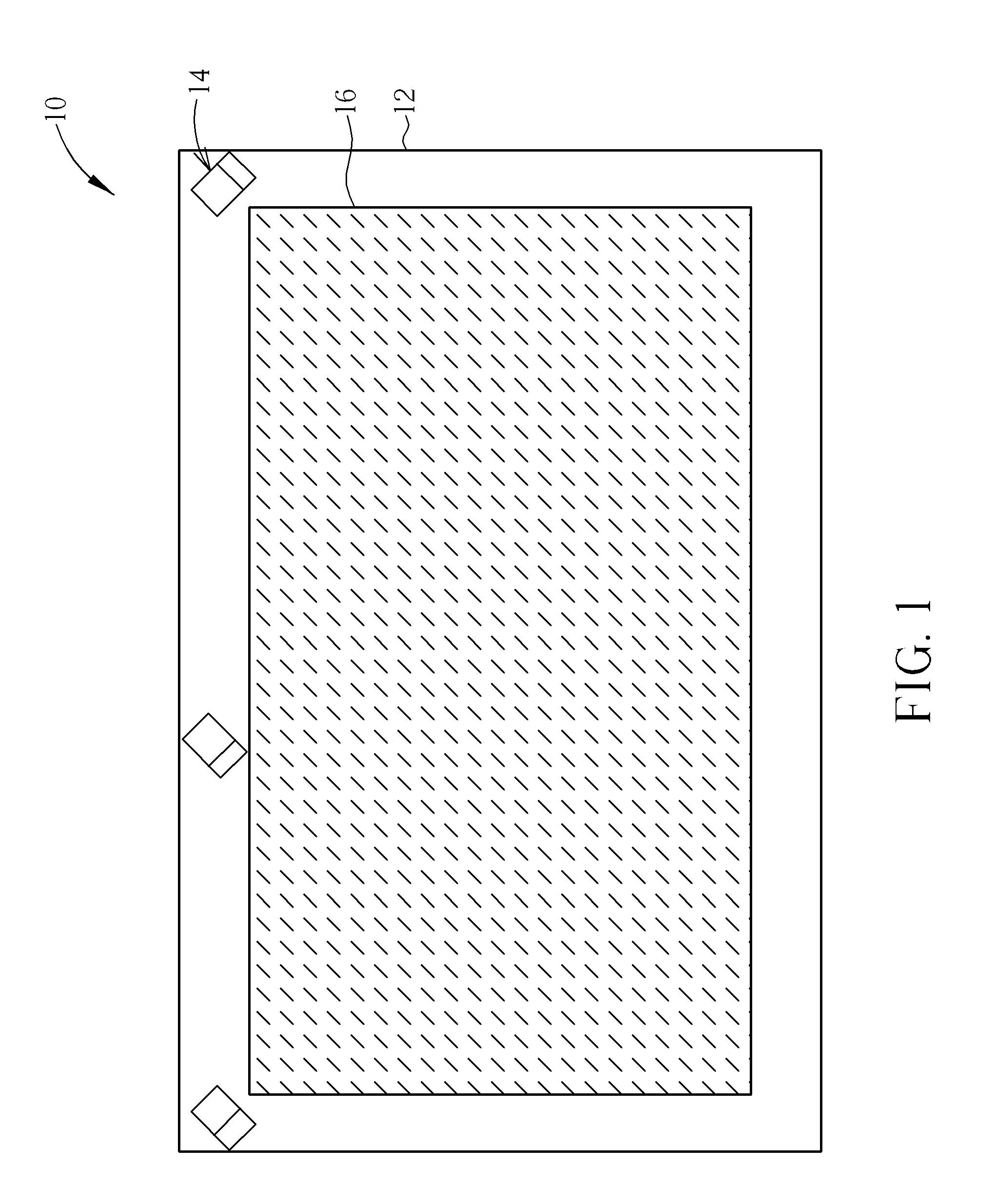
[0014]Please refer to FIG. 1, which is a diagram of an optical touch module 10 according to an embodiment of the invention. As shown in FIG. 1, the optical touch module 10 includes a screen 12 and at least one optical positioning device 14 (three shown in FIG. 1). The optical positioning devices 14 are disposed at an upper-left corner, an upper side, and an upper-right corner of the screen 12, respectively, but are not limited thereto. For example, there can be only the upper-left and the upper-right corners of the screen 12 having the optical positioning device 14 disposed thereon for simplifying the configuration of the optical touch module 10. The screen 12 has a touch surface 16 for a user to perform touch operations.

[0015]Next, please refer to FIG. 2 and FIG. 3. FIG. 2 is an exterior diagram of the optical positioning device 14 in FIG. 1. FIG. 3 is an interior diagram of the optical positioning device 14 in FIG. 2. As shown in FIG. 2 and FIG. 3, the optical touch module 14 incl...


PUM


Abstract

An optical touch module includes a screen and at least one optical positioning device disposed on the screen. The optical positioning device includes a case, at least one light emitting unit, a circuit board, a transparent diffusing part and an image capturing unit. The light emitting unit is disposed on case for emitting invisible light. The circuit board is electrically connected to the light emitting unit for controlling the light emitting unit. The transparent diffusing part is disposed at a light emitting side of the light emitting unit. A bar structure is formed on a light entrance surface of the transparent diffusing part for scattering the invisible light to be distributed over a touch surface of the screen. The image capturing unit is disposed on the case to capture an optical image for a touch object on the touch surface when the touch object is illuminated by the invisible light.

Description

BACKGROUND OF THE INVENTION[0001]1. Field of the Invention[0002]The invention relates to an optical touch module, and more specifically, to an optical touch module capable of increasing a light emitting angle of a light emitting unit disposed therein.[0003]2. Description of the Prior Art[0004]In general, a conventional optical touch module utilizes a light interruption method or a direct image capturing method to detect a position of a user's finger on a touch surface. Both of the two methods utilize two (or three) image capturing devices and a near-infrared light emitting device. The said two image capturing devices are usually disposed at upper-left and upper-right corners of a touch screen, respectively. The difference between the two methods is that the light interruption method utilizes a background lighting design, in which a reflective bar or a near-infrared light emitting bar is disposed around the touch screen. In the light interruption method, a user's finger is taken as a...

Claims


Application Information

Patent Timeline
IPC IPC(8): G06F3/042
CPCG06F2203/04109G06F3/0428
Inventor HUANG, PO-LIANGLIU, CHIA-JUI
Owner WISTRON CORP
Learn More