
Fixing structure of a faucet and an operating method thereof

a fixing structure and faucet technology, applied in water installations, metal working devices, manufacturing tools, etc., can solve the problems of limiting the installation space and having a complicated installation, and achieve the effect of increasing the engagement effect, tight engaging function, and strong structur

Active Publication Date: 2012-06-07
GLOBE UNION INDAL
View PDF1 Cites 31 Cited by
  • Summary
  • Abstract
  • Description
  • Claims
  • Application Information

AI Technical Summary

Benefits of technology

[0007]The primary object of the present invention is to provide a fixing structure of a faucet and an operating method thereof that is capable of overcoming the shortcomings of the conventional fixing structure of a faucet.
[0021]Thereby, the fitting seat is fitted directly during installing the faucet, thus positioning the fitting seat quickly and easily without a rotating operation.
[0022]The positioning device is capable of being operated on the support plate to position the faucet easily and quickly.
[0023]The projections are fixed around an inner surface of the fitting seat and located at the top end of the opening of the support plate to arrange the screwing elements and the engagement blocks so that a receiving space of the channel of the fitting seat are increased to insert the inlet pipe unit easily.
[0025]The engagement block is comprised of the metal base and the plastic clamping piece to obtain a strong structure and a tight engaging function, such that the contacting portion contacts with the bottom wall of the support plate tightly. Also, the rib of the plastic clamping piece is applied to increase an engagement effect.

Problems solved by technology

However, many related components of such a conventional device for the top mounting of the faucet have to be installed below the water tank, limiting installing space and having a complicate installation.

Method used


Image

  • Fixing structure of a faucet and an operating method thereof
  • Fixing structure of a faucet and an operating method thereof
  • Fixing structure of a faucet and an operating method thereof

Examples


Embodiment Construction

[0046]The present invention will be clearer from the following description when viewed together with the accompanying drawings, which show, for purpose of illustrations only, the preferred embodiment in accordance with the present invention.

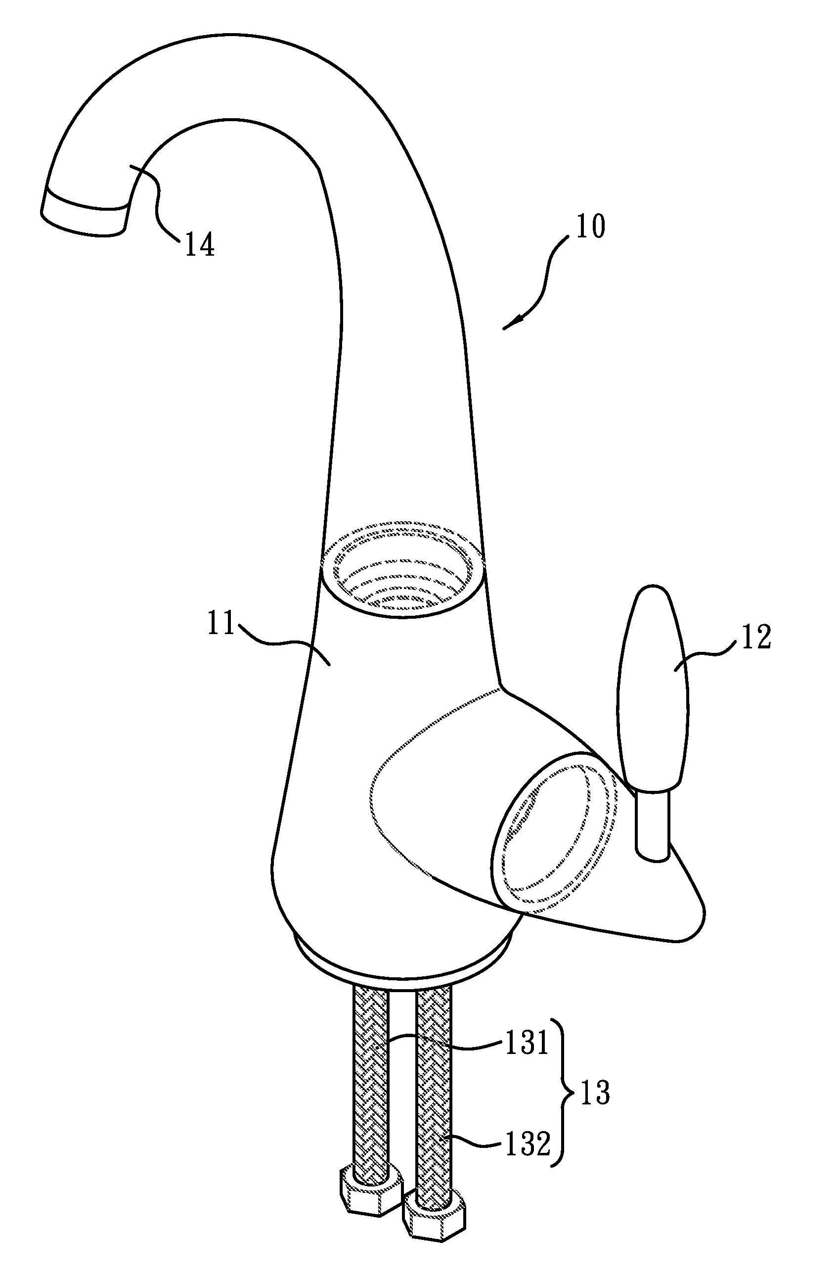
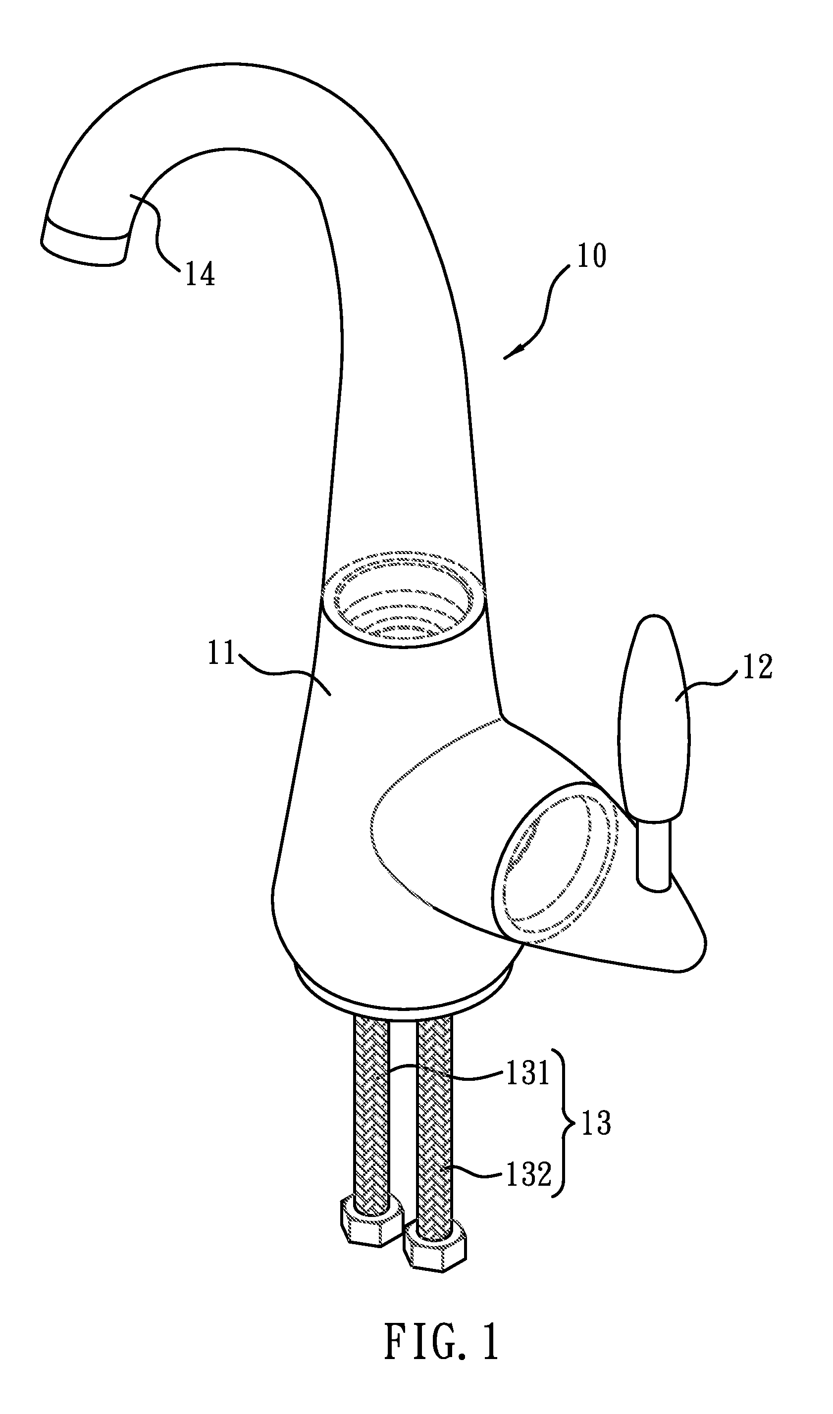
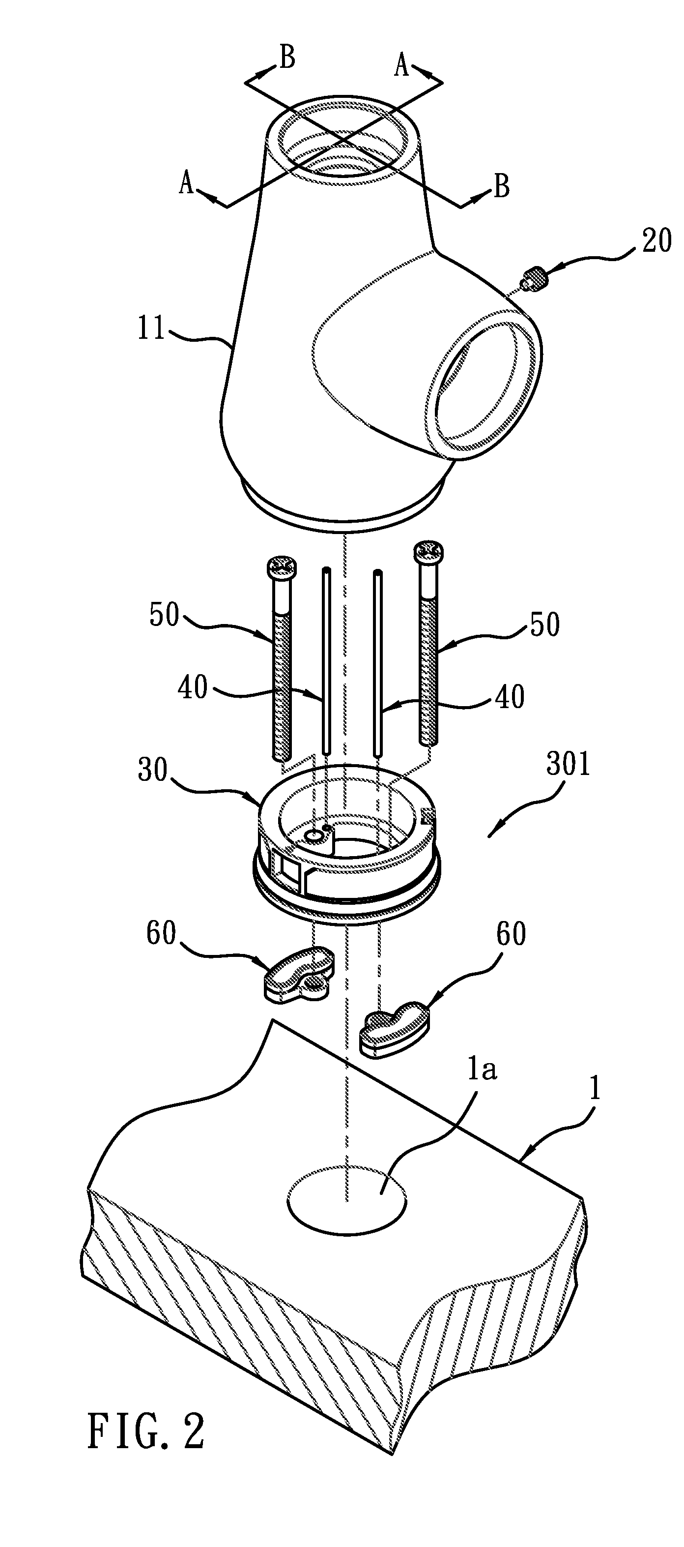
[0047]Referring to FIGS. 1-4, a fixing structure of a faucet according to a preferred embodiment of the present invention comprises a faucet 10, a locking member 20, and a positioning device 301.

[0048]The faucet 10 is fixed on a support plate 1 with an opening la, and the support plate 1 is used in a kitchen cupboard equipped with a water tank, wherein the faucet 10 is fixed on the support plate 1 of the water tank.

[0049]The faucet 10 in this embodiment is a single-handle faucet and comprises a housing 11, the housing 11 includes a valve (not shown) to mix cold and hot waters together disposed therein and an operating bar 12 disposed on one side thereof to be rotated to control the valve, and the valve includes an inlet pipe unit 13 connected wit...


PUM


Abstract

A fixing structure of a faucet fixed on a support plate with an opening and contains the faucet including a housing having a mouth and a through aperture; the faucet also including an inlet pipe unit; a locking member being operated to move between an engaging position and a disengaging position along the through aperture; a positioning device including a fitting seat having a bottom face, a channel defined therein to receive the inlet pipe unit of the faucet, at least one slot disposed along an outer surface thereof to slide the locking member located at the engaging position, the slot including at least one tooth and at least one retaining recess such that the locking member passes through the tooth to be retained in the retaining recess and is limited by the tooth to move so that the mouth is fixed to the fitting seat.

Description

BACKGROUND OF THE INVENTION[0001]1. Field of the Invention[0002]The present invention relates to a fixing structure of a faucet fixed on a support plate and an operating method thereof.[0003]2. Description of the Prior Art[0004]A conventional device for a top mounting of a faucet disclosed in U.S. Pat. No. 5,535,776 contains a fitting seat inserted into an opening of a support plate used in a kitchen equipped with a water tank, and the fitting seat includes a column with screws extending downward to the support plate and used to receive a body of the faucet, the column of the fitting seat includes a plastic pad, a spaced ring, and a metal retaining loop fitted thereon and screwed with a nut. A user applies a torque wrench to insert a screwing element into an orifice of a vertical wall of the fitting seat via a casing of the faucet to limit a relative movement between the faucet and the fitting seat, thus assembling the faucet.[0005]However, many related components of such a conventi...

Claims


Application Information

Patent Timeline
IPC IPC(8): E03C1/04B23P11/00
CPCE03C1/0402E03C2001/0416Y10T29/49947
Inventor LI, CHUNHUNGHSU, WEIMIENWU, YONGJUN
Owner GLOBE UNION INDAL
Learn More