Method of Movement Compensation for a Weapon

Inactive Publication Date: 2012-05-31
LOWREY III JOHN WILLIAM
View PDF3 Cites 21 Cited by
  • Summary
  • Abstract
  • Description
  • Claims
  • Application Information

AI Technical Summary

Benefits of technology

[0016]A method is provided for stabilizing an image through an optical scope and compensating for movement of a weapon directing a projectile along a line of sight, comprising: providing an image stabilization device for an optical scope mounted on a weapon, wherein the image stabilization device includes a sensor to detect motion of the weapon; providing a trigger release device operatively connected to a trigger on the

Problems solved by technology

A significant limitation of shooting accuracy is presented by unsteadiness of the firearm.
However, most other shooters must be content with imperfect supports for their firearms.
For example, a standing shooter hand-holding a rifle results in a relatively unstable condition, and most shooters place the rifle in contact with a fixed object, such as a tree, bipod, or other stable platform.
With accurate rifles capable of accuracies of better than one minute of angle or about one inch per hundred yards, even slight movements of the rifle can lead to inaccuracies far in excess of the capability of the rifle.
Even a shift of only 0.01 inch by the muzzle of the rifle can generate a significant inaccuracy in perfect shooting conditions.
Moreover, factors such as wind, the shooter's breathing, and heartbeat can generate deviations in aim which will adversely affect the point of impact of the bullet.
The motion or shake that causes shooting inaccuracy also presents a visual problem.
High-powered riflescopes magnify the motion, thus blurring the image.
This makes it difficult to detect, acquire, and identify targets.
Oftentimes, a shooter might prefer a higher-powered rifle scope for accuracy, except that the shaky image in actual use makes such higher magnification impractical.
Additionally, the effect of mirage produced by atmospheric convection currents viewed over large distances can further complicate the aiming process and introduce undesirable inaccuracies.
However, when it comes to improving accuracy, there are no viable optical stabilizers for small arms, such as rifles and pistols, because although the image is stable, the lens train and the barrel continue to move.
In practice, the shooter quickly identifies his target and centers the target in the stabilized image, but he still has no way of knowing when the barrel is aligned with the target.
The barrel continues to move relative to the stabilized image due to unsteadiness in the position due to involuntary factors such as heartbeat, breathing, and muscular activity.
While apparently suitable for aiming large weapon systems, it does not appear to be suitable for applications where a high quality image, and small size, low weight, low cost, and simplicity are desired.
Moreover, it appears unsuited to adapt to existing rifle scopes.
Thus, the Philbrick system is further unsuitable for adaptation to convention rifles using mechanical triggers.

Method used


Image

  • Method of Movement Compensation for a Weapon
  • Method of Movement Compensation for a Weapon
  • Method of Movement Compensation for a Weapon

Examples


Embodiment Construction

[0039]Before the subject invention is further described, it is to be understood that the invention is not limited to the particular embodiments of the invention described below, as variations of the particular embodiments may be made and still fall within the scope of the appended claims. It is also to be understood that the terminology employed is for the purpose of describing particular embodiments, and is not intended to be limiting. Instead, the scope of the present invention will be established by the appended claims.

[0040]In this specification and the appended claims, the singular forms “a,”“an,” and “the” include plural reference unless the context clearly dictates otherwise. Unless defined otherwise, all technical and scientific terms used herein have the same meaning as commonly understood to one of ordinary skill in the art to which this invention belongs.

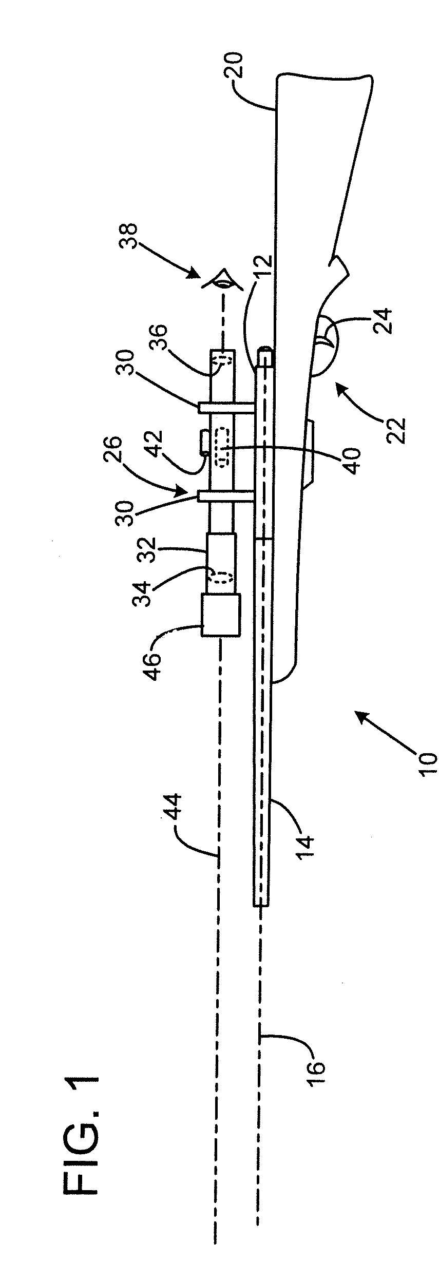
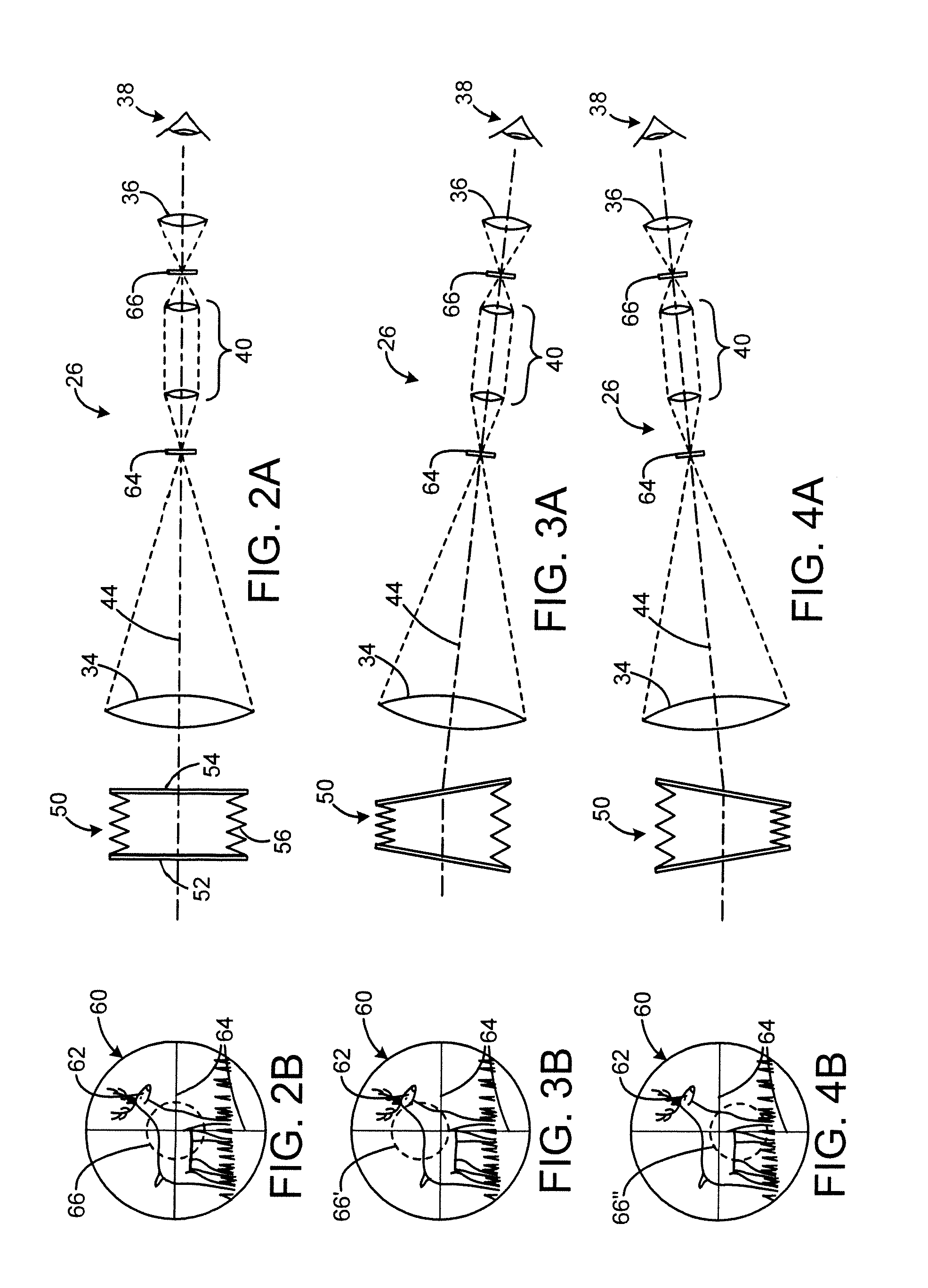
[0041]Optical Stabilization

[0042]Prior to describing the movement compensation methods that are the focus of the presen...


PUM


Abstract

A method for stabilizing an image and compensating for movement of a weapon is provided, comprising: providing an image stabilization device for an optical scope mounted on a weapon, wherein the image stabilization device includes a sensor to detect motion of the weapon; providing a trigger release device operatively connected to a trigger on the weapon; detecting movement of the weapon by the sensor; generating an output signal from the sensor, wherein the output signal corresponds to the position and velocity of the weapon in a plane perpendicular to the line of sight; processing the output signal to determine an optimal release period, and then generating a release signal during the release period; and using the release signal to activate the trigger release.

Description

CROSS-REFERENCE TO RELATED APPLICATIONS[0001]This application is a continuation-in-part and claims the benefit of nonprovisional patent application Ser. No. 11 / 076,340 filed Mar. 8, 2005.STATEMENT REGARDING FEDERALLY SPONSORED RESEARCH OR DEVELOPMENT[0002]Not applicable.THE NAMES OF THE PARTIES TO A JOINT RESEARCH AGREEMENT[0003]Not applicable.INCORPORATION-BY-REFERENCE OF MATERIAL SUBMITTED ON COMPACT DISC[0004]Not applicable.BACKGROUND OF THE INVENTION[0005]1. Field of the Invention[0006]This invention relates to methods for optical stabilization and movement compensation to improve the accuracy of small arms and similar systems.[0007]2. Description of Related Art[0008]A significant limitation of shooting accuracy is presented by unsteadiness of the firearm. Bench-rest competition shooters employ stable platforms for their rifles to remove this source of motion. However, most other shooters must be content with imperfect supports for their firearms. For example, a standing shooter...

Claims


Application Information

Patent Timeline
IPC IPC(8): G06G7/80
CPCF41C27/22F41G1/38F41G3/06F41G11/00G02B23/14G02B27/646F41G3/12F41G3/08
Inventor LOWREY, III, JOHN WILLIAM
Owner LOWREY III JOHN WILLIAM
Why Eureka
Try Eureka