
Induction regulator block

a technology of induction regulator and manifold, which is applied in the direction of combustion air/fuel air treatment, fuel thermal treatment, air intake for fuel, etc., can solve the problems of increased cost and likelihood of mechanical failure, complex design, and difficult retrofitting, so as to improve the efficiency of the internal combustion engine

Inactive Publication Date: 2012-05-31
KENNEDY
View PDF11 Cites 6 Cited by
  • Summary
  • Abstract
  • Description
  • Claims
  • Application Information

AI Technical Summary

Benefits of technology

Improves combustion efficiency, reduces fuel consumption and emissions, and simplifies retrofitting by promoting effective fuel vaporization and atomization through enhanced fuel-air mixing.

Problems solved by technology

These prior art devices each suffer from one or more of the following disadvantages: they are overly complex in design, giving rise to additional cost and likelihood of mechanical failure; they are difficult to retrofit; they do not work satisfactorily in practice to improve engine performance; they do not work satisfactorily in practice to decrease engine emissions.

Method used


Image

  • Induction regulator block
  • Induction regulator block
  • Induction regulator block

Examples


examples

[0069]A Ford Focus 1.6 engine was tested to ascertain the emissions and torque of an engine incorporating the manifold block of the present invention inserted between a conventional manifold and a conventional cylinder head. These tests sought to identify change in emissions, BHP and torque which occurred when different sized blocks in accordance with the invention were fitted on the vehicle.

[0070]In order to fit the new block the conventional manifold, fuel rail, and injector were first removed, exposing the cylinder head. The block of the invention was then fitted on the cylinder head. For the purpose of these experiments it was in some cases found necessary to secure a gasket between the cylinder head and the block to make the connection airtight. In this case the gasket was fitted to the underside of the manifold block. The manifold block is then carefully placed on top of the cylinder head and the original inlet manifold is then fitted on top of the manifold block, again if nec...


PUM


Abstract

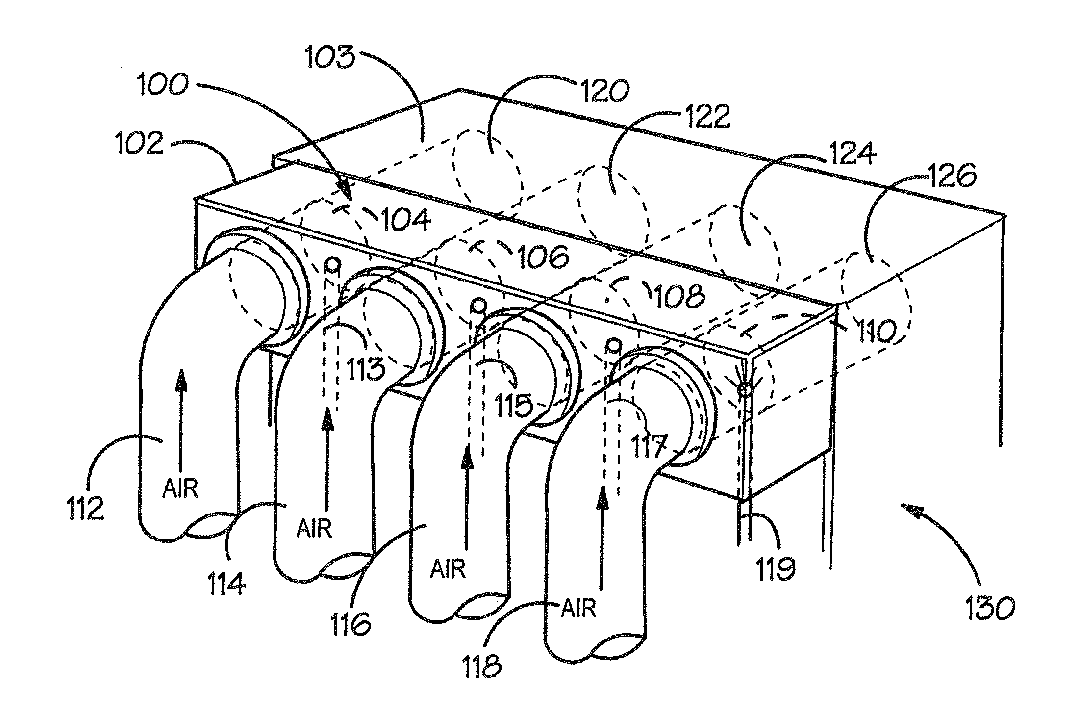
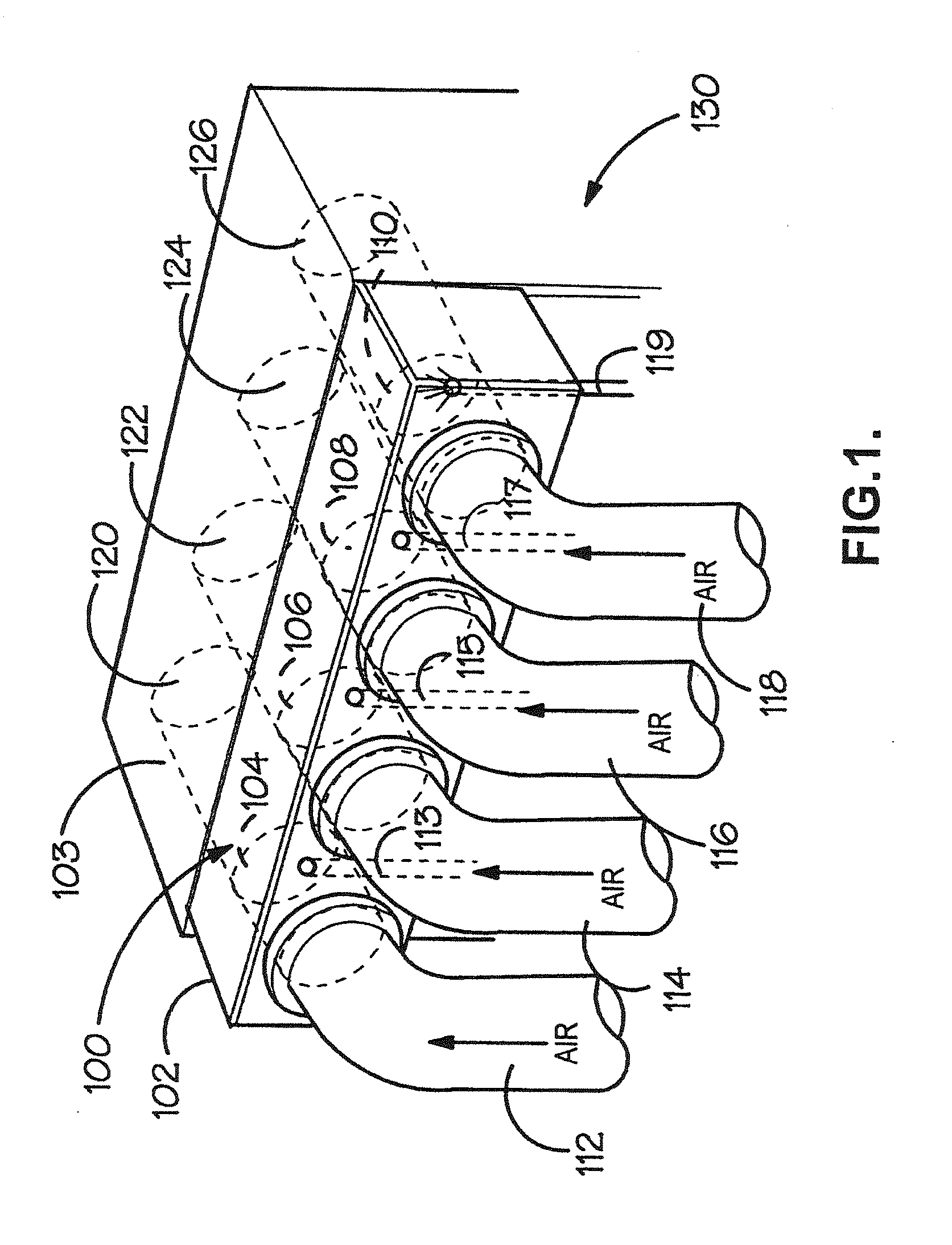
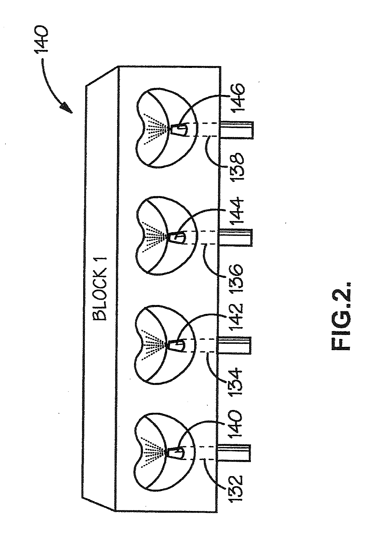
The invention provides a manifold block for improving the efficiency of an internal combustion engine. The manifold block is arranged to be located between an inlet manifold and a cylinder head of the engine, and comprises a block of material having at least one manifold channel there through. The manifold channel has an input end and an output end, wherein the input end is connected to the inlet manifold, and the output end is connected to the cylinder. The manifold channel includes at least one injector head channel located towards its input end and adapted to receive a fuel injector. The manifold block may also incorporate one or induction regulators for improving the efficiency of fuel / air mixing in the manifold channels.

Description

BACKGROUND OF THE INVENTION[0001]1. Field of the Invention[0002]The present invention relates to a manifold block for an internal combustion engine and in particular a manifold block that promotes mixing of fuel and air in the engine upstream of the cylinder head, improving the efficiency, emissions profile and / or power of the engine. The block may also incorporate an induction regulator further to facilitate fuel / air mixing.[0003]2. Description of the Related Art[0004]It is well known to use a fuel injector to control the fuel / air mixture ratio in an engine. Conventional fuel injection systems are generally adapted to monitor the amount of fuel supplied to the engine, or to each cylinder thereof, the timing and duration of each injection event being controlled to provide a desirable fuel / air mixture in the cylinder. However, conventional injector systems are generally not designed to optimize the mixing of fuel and air upstream of the cylinder(s), and the present invention seeks to...

Claims


Application Information

Patent Timeline
Patent Type & Authority Applications(United States)
IPC IPC(8): F02M35/10F02M29/02F02M29/04F02M31/135F02M35/112
CPCF02M29/02F02M29/04F02M31/135F02M35/10085F02M35/10104F02M35/10216Y02T10/126F02M35/10321F02M35/10327F02M35/10354F02M35/112Y02T10/146F02M35/10262Y02T10/12F02M35/10F02M29/00F02M35/104
Inventor KENNEDY
Owner KENNEDY
Learn More