Coaxial connector with enhanced shielding
- Summary
- Abstract
- Description
- Claims
- Application Information
AI Technical Summary
Benefits of technology
Problems solved by technology
Method used
Image
Examples
Embodiment Construction
[0021]The disclosure provided in the following pages describes examples of some embodiments of the invention. The designs, figures, and description are non-limiting examples of embodiments they disclose. For example, other embodiments of the disclosed device and / or method may or may not include the features described herein. Moreover, disclosed advantages and benefits may apply to only certain embodiments of the invention and should not be used to limit the disclosed invention.
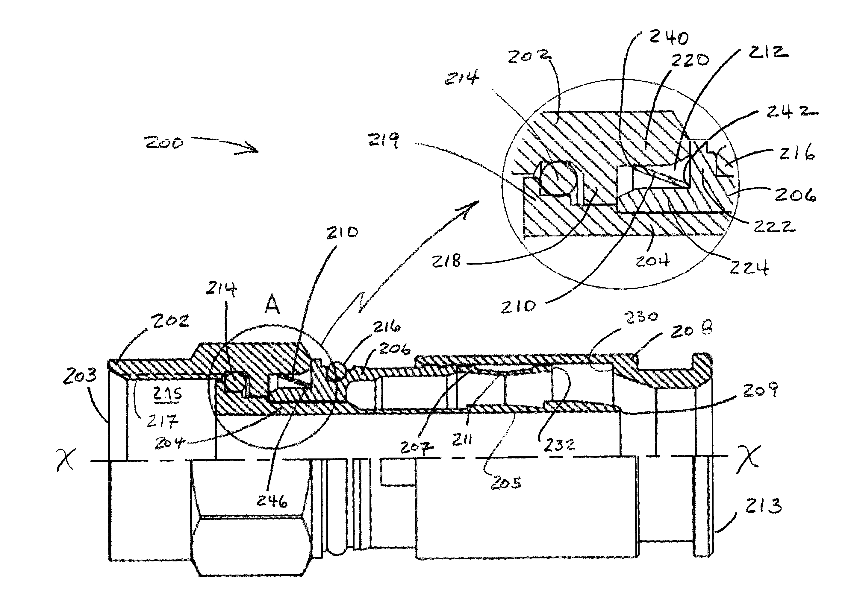
[0022]FIG. 2 shows a male F-Type coaxial cable connector in accordance with the present invention 200. The connector includes a post 204, a flange or flange-like structure 219 opposite a trailing end of the post 209, a rotatable front attachment nut surrounding the flange 202, and a connector body 206 affixed to the post adjacent to the nut. The nut end of the connector is referred to as the forward end 203 and the opposite end of the connector is referred to as the trailing end 213. A nut forward cavity 215 i...
PUM
| Property | Measurement | Unit |
|---|---|---|
| Resilience | aaaaa | aaaaa |
Abstract
Description
Claims
Application Information
 - R&D
- Intellectual Property
- Life Sciences
- Materials
- Tech Scout
- Unparalleled Data Quality
- Higher Quality Content
- 60% Fewer Hallucinations
Browse by: Latest US Patents, China's latest patents, Technical Efficacy Thesaurus, Application Domain, Technology Topic, Popular Technical Reports.
© 2025 PatSnap. All rights reserved.Legal|Privacy policy|Modern Slavery Act Transparency Statement|Sitemap|About US| Contact US: help@patsnap.com


