Torsion spring wing deployment initiator

a technology of spring wing and initiator, which is applied in the direction of direction controllers, instruments, weapons, etc., can solve the problems of guidance system failure, limited speed of missile spin, and insufficient centripetal energy by itself to enable the wings

Active Publication Date: 2012-05-17
BAE SYST INFORMATION & ELECTRONICS SYST INTERGRATION INC
View PDF10 Cites 7 Cited by
  • Summary
  • Abstract
  • Description
  • Claims
  • Application Information

AI Technical Summary

Benefits of technology

[0011]The wing deployment mechanism of the present invention is light in weight and fits into a limited space within the guidance wing storage region of the missile or rocket. It uses a combination of torsion springs and lever arms to apply the required additional deployment force to the guidance wings as they break through the cover seals. In embodiments, each of the guidance wings is pushed by two “extreme duty” torsion springs and two lever arms.

Problems solved by technology

However, there is a practical limit to how rapidly a missile can be spun.
This amount of centripetal energy may not be sufficient by itself to enable the wings to burst through the frangible slot covers.
As a result, some weapons that include deployable folded guidance wings and frangible wing slot covers have demonstrated a tendency for the guidance system to fail due to a lack of proper guidance wing deployment.
However, this approach can be undesirable due to the violent forces produced by the explosives, and due to concerns about the safety and the long-term chemical stability of the explosives during storage of the weapon.
However, only very limited space is available for a wing deployment initiator to occupy.
Therefore, it can be very difficult to provide a mechanical wing deployment initiator which can provide sufficient force to enable the guidance wings to break through the frangible covers while also fitting within the available space and remaining sufficiently light in weight.

Method used


Image

  • Torsion spring wing deployment initiator
  • Torsion spring wing deployment initiator
  • Torsion spring wing deployment initiator

Examples


Embodiment Construction

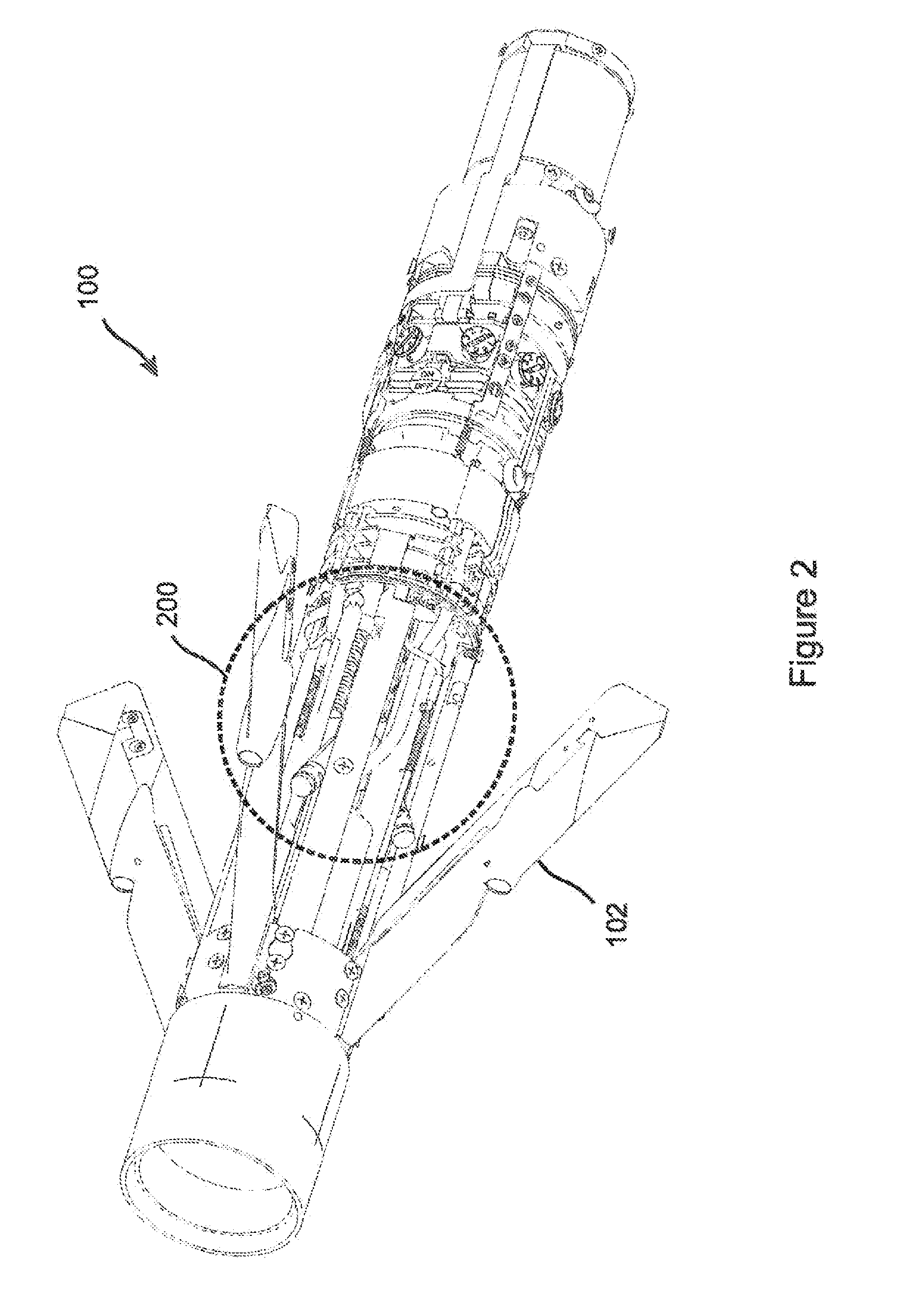
[0037]The present invention is a wing deployment initiating mechanism which provides added wing deployment force during the initial deployment of guidance wings on folded wing missiles and rockets, so as to augment the centrifugal wing deployment force during the initial phase of wing deployment and ensure that the wings are able to break through frangible seals which cover the wing deployment slots. After bursting through the seals, the wings are fully deployed by the centrifugal force which arises from the spinning of the missile in flight.

[0038]With reference to FIG. 1, some aerial rockets and missiles 100 include guidance wings 102 which are typically folded within the main fuselage 104 in a stowed configuration until the weapon is launched, at which point the wings 102 are released and deployed through wing slots 106. One example is the Advanced Precision Kill Weapon System (APKWS) laser guided missile 100. FIG. 1 illustrates an APKWS 100 having just been launched from a helico...


PUM


Abstract

A compact, purely mechanical wing deployment assisting mechanism uses torsion springs and lever arms to apply a deploying force to a guidance wing during its initial deployment through a wing slot in a rocket or missile, thereby assisting the wing to burst through a cover seal protecting the wing slot. The wings are then fully deployed by centrifugal force. Various embodiments include two “extreme duty” springs and two lever arms per wing, working in parallel. Embodiments provide a total of at least 24 pounds of force per wing at the end of a spring travel of 0.30 inches. In some embodiments, the entire mechanism weighs less than 0.5 pounds and / or occupies less than 2.5 cubic inches per wing. In embodiments, an assembled group, including two springs and two lever arms, is located between each pair of wings, whereby each assembled group applies one lever arm to each adjoining wing.

Description

RELATED APPLICATIONS[0001]This application claims the benefit of U.S. Provisional Application No. 61 / 322,461, filed Apr. 9, 2010, herein incorporated by reference in its entirety for all purposes.STATEMENT OF GOVERNMENT INTEREST[0002]The invention was made with United States Government support under Contract No. W31P4Q-06-C-0330 awarded by the Navy. The United States Government has certain rights in this invention.FIELD OF THE INVENTION[0003]The invention relates to ballistic weaponry, and more particularly to apparatus for deploying guidance wings on folding fin aerial rockets and missiles.BACKGROUND OF THE INVENTION[0004]Aerial rockets and missiles which include folded, deployable guidance wings have been in use at least since the late 1940's, with the FFAR (Folding Fin Aerial Rocket) being used in the Korean and Vietnam conflicts, and the more recent Hydra 70 family of WAFAR (Wrap-Around Fin Aerial Rocket) and Advanced Precision Kill Weapon System (APKWS) laser guided missile. Fo...

Claims


Application Information

Patent Timeline
Patent Type & Authority Applications(United States)
IPC IPC(8): F42B10/14F42B10/64
CPCF42B10/14
Inventor BARRY, WILLIAM D.KRUEGER, MICHAEL J.PIETRZAK, AMY
Owner BAE SYST INFORMATION & ELECTRONICS SYST INTERGRATION INC
Why Eureka
Try Eureka