
Method for compensating for valve lift deviation between engines equipped with cvvl mechanism

a technology of cvvl mechanism and valve lift, which is applied in the direction of machines/engines, instruments, output power, etc., can solve the problem of generating a valve lift deviation between engines, and achieve the effect of quality robustness

Active Publication Date: 2012-05-10
HYUNDAI MOTOR CO LTD +1
View PDF35 Cites 11 Cited by
  • Summary
  • Abstract
  • Description
  • Claims
  • Application Information

AI Technical Summary

Benefits of technology

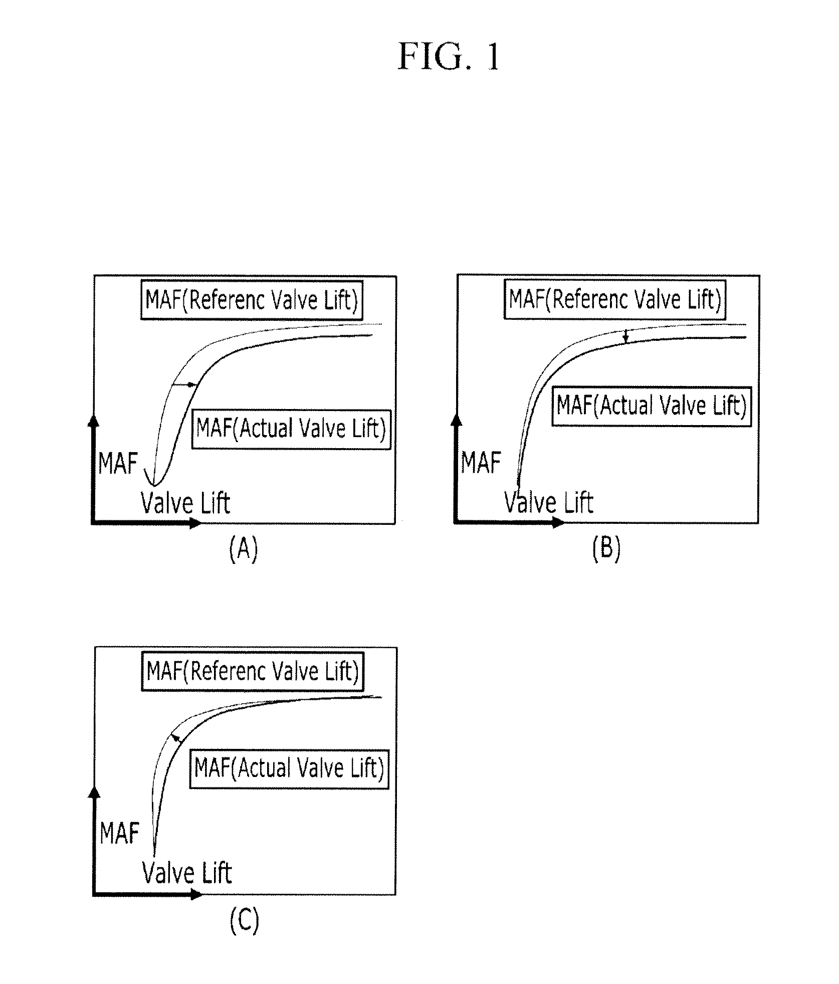
[0021]As described above, various types of deviations in valve lift can be solved depending on a learned value of valve lift deviation, and the engines can have the same characteristics because a deviation in intake air flow rate can be minimized by learning the valve lift of the engines. Moreover, quality robustness is attained by compensating for a mass deviation between the engines with the CVVL mechanism, and it is possible to cope with changes in the hardware deviations of the CVVL mechanism.

Problems solved by technology

However, despite the correction, the actual air flow rate and the flow rate of intake air into the cylinder may vary by a number of factors, and this may generates a valve lift deviation between engines.

Method used


Image

  • Method for compensating for valve lift deviation between engines equipped with cvvl mechanism
  • Method for compensating for valve lift deviation between engines equipped with cvvl mechanism
  • Method for compensating for valve lift deviation between engines equipped with cvvl mechanism

Examples


Embodiment Construction

[0029]Reference will now be made in detail to various embodiments of the present invention(s), examples of which are illustrated in the accompanying drawings and described below. While the invention(s) will be described in conjunction with exemplary embodiments, it will be understood that present description is not intended to limit the invention(s) to those exemplary embodiments. On the contrary, the invention(s) is / are intended to cover not only the exemplary embodiments, but also various alternatives, modifications, equivalents and other embodiments, which may be included within the spirit and scope of the invention as defined by the appended claims.

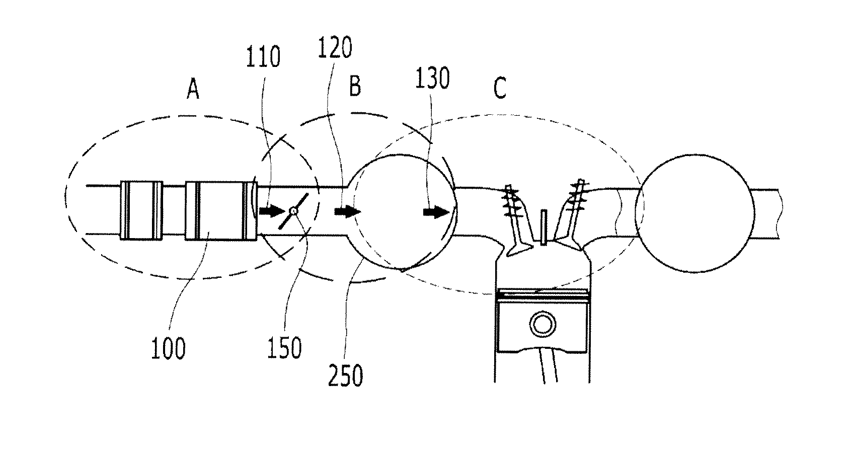
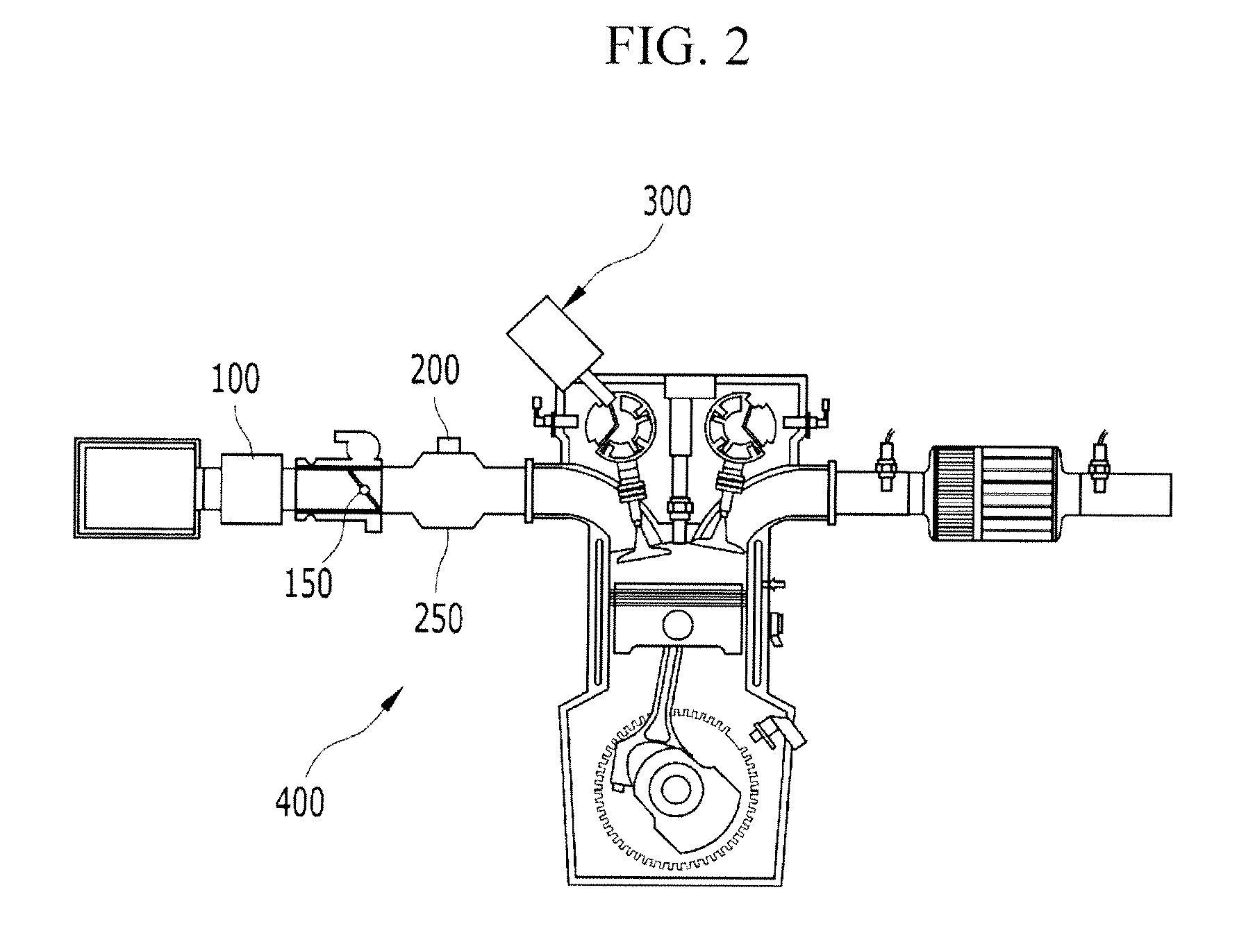
[0030]FIG. 2 is a schematic view of the engine equipped with the CVVL mechanism according to various embodiments of the present invention, which schematically shows mounting positions of an MAF sensor 100 and an MAP sensor 200 and a CVVL system according to the present invention. FIG. 3 shows the flow of intake air into a cylinder acc...


PUM


Abstract

A method is provided for compensating for a valve lift deviation between engines equipped with a CVVL mechanism, in which the valve lift deviation is compensated for by an MAF sensor for measuring a reference air flow rate and an MAP sensor for measuring the pressure of an intake manifold. The method includes determining whether learning conditions for learning a valve lift deviation are met; after the determination, comparing a value MAP_MES measured by the MAP sensor and a modeled pressure MAP_MDL of a surge tank; if the MAP_MES value and the MAP_MDL value are different, learning the valve lift, and after the learning, calculating the final valve lift by adding the learned value of the valve lift to the basic valve lift characteristics. Various types of deviations in valve lift can be solved by using a learned value of valve lift deviation, the engines can have the same characteristics because a deviation in intake air flow rate is minimized by learning the valve lift of the engines, and the quality of the engine of the CVVL mechanism can be improved.

Description

CROSS-REFERENCE TO RELATED APPLICATION[0001]This application claims priority to and the benefit of Korean Patent Application No. 10-2010-0109400 filed Nov. 4, 2010, the entire contents of which application is incorporated herein for all purposes by this reference.BACKGROUND OF INVENTION[0002]1. Field of Invention[0003]The present invention relates to a method for compensating for a valve lift deviation between engines equipped with a CVVL mechanism, and more particularly, to a method for compensating for a valve lift deviation by learning the valve lift and adding a learned value so that a pressure measured by a MAP sensor and a modeled MAP value are equal to each other.[0004]2. Description of Related Art[0005]In a method for detecting a flow rate of intake air into a cylinder from an engine equipped with a conventional CVVL (continuous variable valve lift) mechanism, the intake air flow rate is measured by a MAF sensor 100 (see FIG. 2). It is usually necessary to perform correction...

Claims


Application Information

Patent Timeline
Patent Type & Authority Applications(United States)
IPC IPC(8): G01M15/04
CPCF01L1/3442F01L2001/0537F01L2800/00Y02T10/18F01L2800/14F01L2820/041F02D13/0207F01L2800/09Y02T10/12
Inventor LEE, JOONSUCK
Owner HYUNDAI MOTOR CO LTD
Learn More