
Method for controlling a transmission coupled to an engine that may be automatically stopped

Inactive Publication Date: 2012-05-10
FORD GLOBAL TECH LLC
View PDF7 Cites 25 Cited by
  • Summary
  • Abstract
  • Description
  • Claims
  • Application Information

AI Technical Summary

Benefits of technology

[0003]An input shaft of a transmission may be tied to a case of a transmission during engine starting. Tying the transmission input shaft to the transmission case allows the transmission to supply an increased load to the engine as compared to when the engine is in neutral so that engine speed may be controlled during an engine start. Additionally, less engine torque may be transmitted to vehicle wheels when the input shaft is coupled to the transmission case instead of vehicle wheels. In this way, a load may be applied to an engine to control engine speed during starting while at the same time limiting torque to accelerate the vehicle to which the engine is coupled. However, if one or more clutches tying up the transmission is supplied oil at a low pressure, the clutch may slip and cause a torque disturbance in the vehicle driveline. Alternatively, if the clutch is supplied oil at a higher pressure, it may take a longer amount of time to release the clutch so that vehicle launch may be delayed. Further, transmission temperatures as well as changes in road grade can affect whether or not a transmission tie-up clutch holds the transmission input shaft in a desired manner. Therefore, a single transmission clutch tie-up oil pressure command may not provide desirable tie-up characteristics during varying vehicle operating conditions.
[0006]The present description may provide several advantages. For example, the approach may reduce vehicle launch variability for engines that are automatically stopped and started. Further, the method may reduce transmission clutch wear since transmission tie-up application and release can be adjusted for operating conditions. Further still, engine emissions may be reduced as compared to systems where engine speed varies due to slipping of the transmission during transmission tie-up.

Problems solved by technology

However, if one or more clutches tying up the transmission is supplied oil at a low pressure, the clutch may slip and cause a torque disturbance in the vehicle driveline.
Alternatively, if the clutch is supplied oil at a higher pressure, it may take a longer amount of time to release the clutch so that vehicle launch may be delayed.
Further, transmission temperatures as well as changes in road grade can affect whether or not a transmission tie-up clutch holds the transmission input shaft in a desired manner.
Therefore, a single transmission clutch tie-up oil pressure command may not provide desirable tie-up characteristics during varying vehicle operating conditions.

Method used


Image

  • Method for controlling a transmission coupled to an engine that may be automatically stopped
  • Method for controlling a transmission coupled to an engine that may be automatically stopped
  • Method for controlling a transmission coupled to an engine that may be automatically stopped

Examples


Embodiment Construction

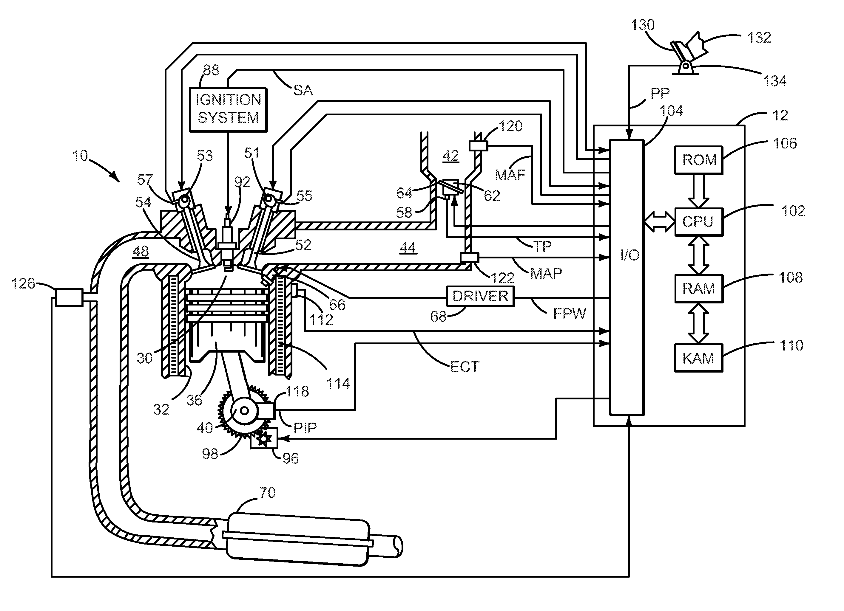
[0014]The present description is related to controlling a transmission coupled to an automatically started engine. In one non-limiting example, the engine may be configured as illustrated in FIG. 1. Further, the engine may be part of a vehicle as illustrated in FIG. 2.

[0015]Engine starting and transmission control may be performed according to the method described by FIG. 6. The method of FIG. 6 may be used to control oil pressure supplied to one or more transmission tie-up clutches during an engine start. Further, the method of FIG. 6 may adjust oil pressure supplied to one or more transmission clutches during an engine start based on vehicle acceleration during a previous engine start. FIGS. 3 and 5 are plots of example engine starts that the present method seeks to avoid, while FIG. 4 is an example engine start that the present method seeks to provide.

[0016]Referring to FIG. 1, internal combustion engine 10, comprising a plurality of cylinders, one cylinder of which is shown in F...


PUM


Abstract

Methods and systems for controlling a transmission coupled to an engine during an engine start are presented. In one example, a method adjusts a transmission tie-up force in response to an indication of transmission slip. The method may improve vehicle launch for stop / start vehicles.

Description

CROSS REFERENCE TO RELATED APPLICATIONS[0001]The present application is a continuation-in-part of U.S. patent application Ser. No. 12 / 833,788, entitled “METHOD FOR CONTROLLING AN ENGINE THAT MAY BE AUTOMATICALLY STOPPED,” filed Jul. 9, 2010, the disclosure of which is hereby incorporated by reference.FIELD[0002]The present description relates to methods and systems for controlling a transmission that is coupled to an engine that may be automatically stopped and started. The method may be particularly useful for engines that are stopped and then restarted while the transmission is in gear.BACKGROUND AND SUMMARY[0003]An input shaft of a transmission may be tied to a case of a transmission during engine starting. Tying the transmission input shaft to the transmission case allows the transmission to supply an increased load to the engine as compared to when the engine is in neutral so that engine speed may be controlled during an engine start. Additionally, less engine torque may be tra...

Claims


Application Information

Patent Timeline
IPC IPC(8): B60W10/02
CPCB60W10/023Y10T477/656B60W10/11B60W10/184B60W30/18018B60W2510/107B60W2510/182B60W2550/12B60W2560/06B60W2710/1083F02N11/0814F16H61/0059F16H2312/04F16H2312/14Y02T10/48B60W10/02B60W10/10Y10T477/78Y10T477/638Y10T477/753B60W10/06B60W2530/213B60W2555/20Y02T10/40
Inventor DOERING, JEFFREY ALLENCICALA, STEVE MICHAELGIBSON, ALEX O'CONNORNEDOREZOV, FELIXBANNERS, ERIC FRANKJIANG, HONGLEVENS, DONALD G.
Owner FORD GLOBAL TECH LLC
Learn More