
Liquid lens, and method for manufacturing same

Inactive Publication Date: 2012-05-10
KYUNGPOOK NAT UNIV IND ACADEMIC COOP FOUND
View PDF2 Cites 25 Cited by
  • Summary
  • Abstract
  • Description
  • Claims
  • Application Information

AI Technical Summary

Benefits of technology

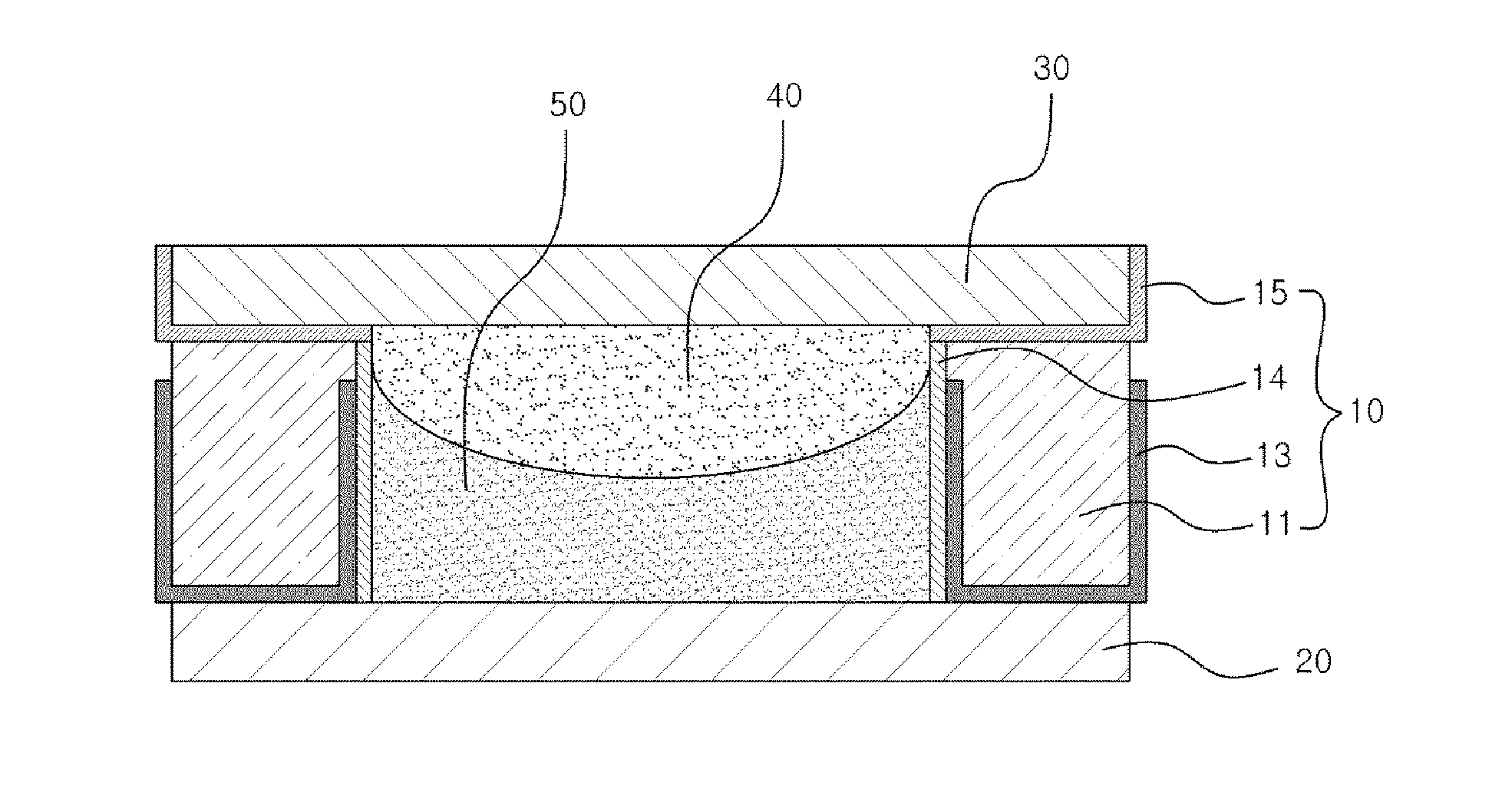
[0024]As described above, according to the liquid lens according to the present invention, the cavity containing the liquid droplet is formed to have a hemispherical shape, so that it is possible to minimize voltage consumption and to efficiently adjust a focus.
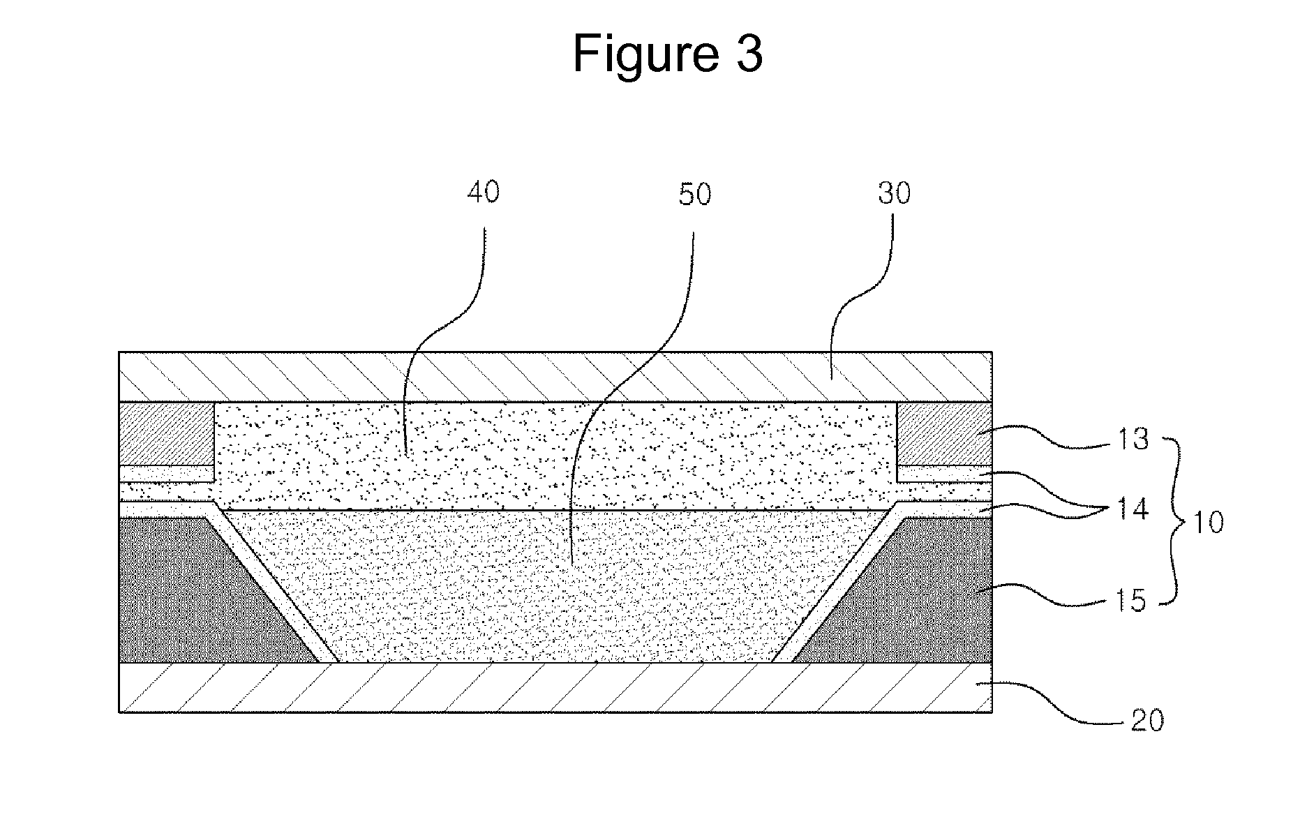
[0025]In addition, according to the liquid lens according to the present invention, the fluid pressure passage is formed on the lower substrate, and the shapes of the liquid droplets contained in the cavity and the upper substrate is deformed in response to the fluid pressure applied through the fluid pressure passage, so that focus adjustment can be performed by adjusting the voltage and the fluid pressure. Accordingly, it is possible to adjust a focus in a wider range.
[0026]In addition, according to the method of manufacturing the liquid lens according to the present invention, the container containing the liquid droplets is produced by using a semiconductor process, so that it is possible to manufacture a liquid lens having a more precise container and to easily perform mass production in comparison with a conventional method of manufacturing a liquid lens.

Problems solved by technology

In this manner, in the conventional high-performance digital camera, since the lens driving unit needs to be installed in order to adjust the focus and magnification, the size of the digital camera is inevitably increased, and it is difficult to miniaturize the high-performance digital camera.
However, the liquid lens has a problem in that it is difficult to inject the conductive liquid droplet and the insulating liquid droplet.
However, the liquid lens having a truncated conical cavity has a problem in that the liquid droplets contained in the cavity is vulnerable to an external impact in comparison with the liquid lens having a cylindrical cavity.
However, this manufacturing method has a limitation in more precisely manufacturing the cavity of the container.

Method used


Image

  • Liquid lens, and method for manufacturing same
  • Liquid lens, and method for manufacturing same
  • Liquid lens, and method for manufacturing same

Examples


first embodiment

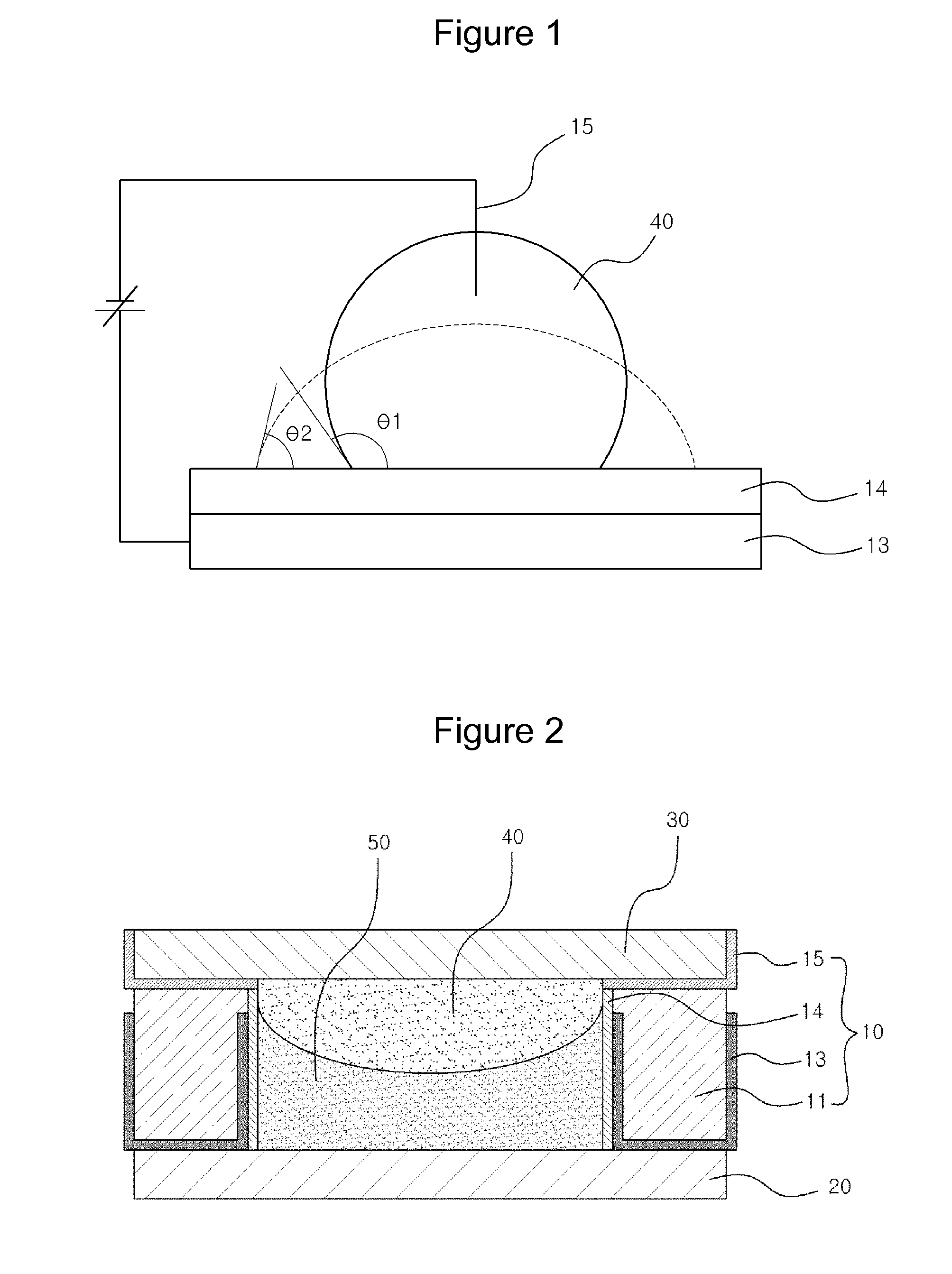
[0059]As illustrated in FIG. 9, the container 700 has the cavity of which the side cross section has a hemispherical shape, and the insulating liquid droplet and the conductive liquid droplet which are not mixed and have the same density are contained in the cavity. The configurations of the container 700 and the upper substrate 800 are the same as those of the first embodiment, and thus, the description thereof is omitted. However, the container according to this embodiment does not include a second electrode.

second embodiment

[0060]FIG. 10 is a perspective view illustrating a fluid pressure plate 810 of the liquid lens according to the Referring to FIG. 10, the fluid_pressure plate 810 according to the present invention includes a fluid pressure passage 812 which functions as a passage for transferring an externally applied pressure to the liquid droplets in the cavity and a second electrode 750 which is formed in the central area of the surface of the fluid pressure passage. It is preferable that the second electrode is configured as a transparent electrode. The fluid pressure plate is disposed so that the fluid pressure passage is engaged with the lower portion of the cavity, and the fluid pressure plate is engaged with the container so that the lower portion of the cavity is sealed. In other words, the bottom surface of the container is sealed by engagement with the fluid pressure plate, and external pressure is exerted through the fluid pressure passage. The second electrode formed on the surface of...


PUM


Abstract

Provided is a liquid lens capable of adjusting a focus by using an electrical signal and / or a fluid pressure. The liquid lens includes a container which has a cavity of which the side cross section has a hemispherical shape and contains an insulating liquid droplet and a conductive liquid droplet which are not mixed in the cavity and have the same density, a lower substrate which is combined with a bottom surface of the container to seal a bottom surface of the cavity, and an upper substrate which is combined with a top surface of the container to seal a top surface of the cavity, wherein the container includes an outer wall where the cavity is formed, a first electrode which is formed on an inner side surface of the outer wall and of which the one end is connected to an external power supply, a first insulating film which is laminated a surface of the first electrode and is in contact with the conductive liquid droplet and the insulating liquid droplet, and a second electrode which is laminated on a portion of a surface of the first insulating film and of which the one end is in contact with the conductive liquid droplet and of which the other end is in contact with the external power supply. Accordingly, it is possible to more efficiently adjust a focus by using a small driving voltage by improving a structure of the cavity of the container.

Description

TECHNICAL FIELD [0001]The present invention relates to a liquid lens and a method of manufacturing a liquid lens, and more particularly, to a liquid lens capable of adjusting a focus by using an electrical signal or by using an electrical signal and a fluid pressure and a method of manufacturing a liquid lens.BACKGROUND ART [0002]In general, a lens module of a high-performance digital camera is configured to include an optical lens made of a glass and a lens driving unit for driving the optical lens. In the lens module, a position of the optical lens is adjusted by using the lens driving unit in order to adjust a focus and a magnification ratio of the optical lens.[0003]In this manner, in the conventional high-performance digital camera, since the lens driving unit needs to be installed in order to adjust the focus and magnification, the size of the digital camera is inevitably increased, and it is difficult to miniaturize the high-performance digital camera.[0004]Therefore, recentl...

Claims


Application Information

Patent Timeline
IPC IPC(8): G02B3/14
CPCG02B26/004G02B3/14
Inventor KONG, SEONG HOKIM, HAK-RINLEE, JUNE KYOO
Owner KYUNGPOOK NAT UNIV IND ACADEMIC COOP FOUND
Learn More