Electro-optical apparatus and electronics device
- Summary
- Abstract
- Description
- Claims
- Application Information
AI Technical Summary
Benefits of technology
Problems solved by technology
Method used
Image
Examples
modification example 1
3-1. Modification Example 1
[0066]FIG. 15 is a diagram illustrating a relation between a position of the liquid crystal panel 100 and a position of a user H. In the above-described embodiment, an example in which the electro-optical apparatus 1 is a two-view display has been described; while, in this modification example 1, the electro-optical apparatus 1 is a three-view display. From a position A, the liquid crystal panel 100 is observed in a direction parallel with a direction in which the liquid crystal panel 100 and the parallax barrier 150 are laminated, and this direction from the position A to the liquid crystal panel 100 is defined as a front-center direction. From a position B, which is located at a position shifting in a right-hand direction from the front-center direction, the liquid crystal panel 100 is observed in an oblique direction relative to a front panel of the liquid crystal panel 100. From a position C, which is located at a position shifting in a left-hand direc...
modification example 2
3-2. Modification Example 2
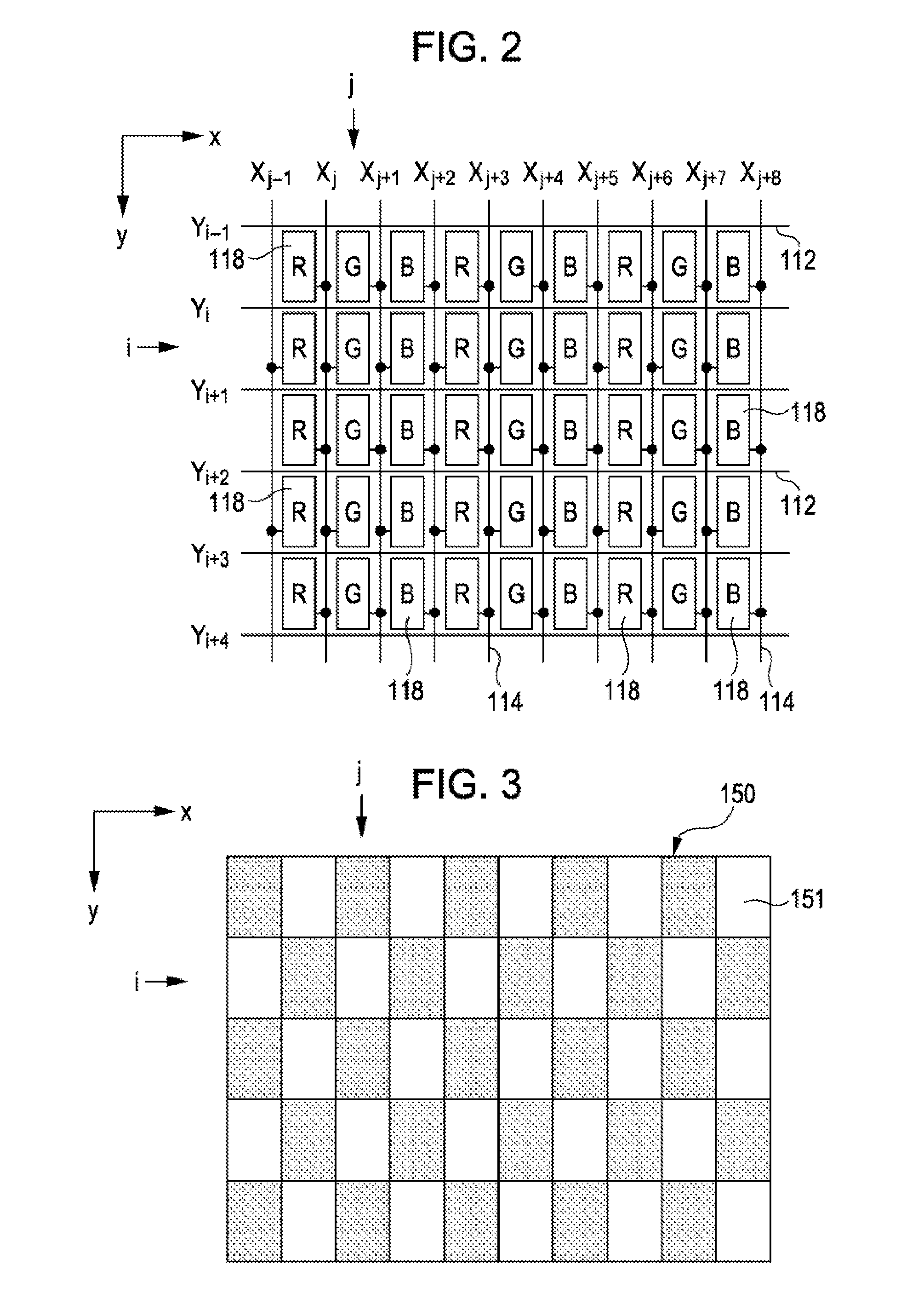
[0074]FIG. 22 is a diagram illustrating an allocation of the pixel electrodes 118 in this modification example 2. In the example shown in FIG. 2, each of the pixel electrodes 118 is vertically long (i.e., in a long shape along the y-axis direction), and pixels each having a different color are arrayed in a short-side direction (i.e., in the x-axis direction). That is, in any one of the rows, pixels of R, G and B are periodically arrayed. In contrast, as shown FIG. 22, each of the pixel electrodes 118 is horizontally long (i.e., in a long shape along the x-axis direction), and pixels each having a different color are arrayed in a short-side direction (i.e., in the y-axis direction). That is, the pixel electrodes 118 each having R, G or B are periodically arrayed in any one of the columns thereof. In this case, the parallax barrier 150 has a configuration obtained by rotating the parallax barrier 150 shown in FIG. 3 by 90 degrees. As described above, the liq...
modification example 3
3-3. Modification Example 3
[0075]FIG. 23 is a diagram illustrating an allocation of the pixel electrodes 118 in this modification example 3. In the above-described embodiment, the example, in which the pixel electrodes 118 correspond to respective pixels, has been described, but one pixel may be configured by a plurality of the pixel electrodes 118. In this modification example 3, three pixels each having R, G or B is treated as a set of (i.e., a unit of) pixels. That is, a group of pixel electrodes corresponding to a set of pixels are connected to the same data line. In any one of columns, each of the TFTs 116 is alternately connected to either of two adjacent data lines for each pixel, that is, for each set of pixels. In other words, a second set of pixels, which is located adjacent the first set of pixels in the y-axis direction, is connected to a data line different from that connected to the first set of pixels. In this case, each of the windows 151 included in the parallax bar...
PUM
 Abstract
Description
Claims
Application Information
 - R&D
- Intellectual Property
- Life Sciences
- Materials
- Tech Scout
- Unparalleled Data Quality
- Higher Quality Content
- 60% Fewer Hallucinations
Browse by: Latest US Patents, China's latest patents, Technical Efficacy Thesaurus, Application Domain, Technology Topic, Popular Technical Reports.
© 2025 PatSnap. All rights reserved.Legal|Privacy policy|Modern Slavery Act Transparency Statement|Sitemap|About US| Contact US: help@patsnap.com


