
Stylus and method of manufacturing the same

a technology of stylus and stylus, which is applied in the field of stylus, can solve the problems of reducing reliability, difficult to manipulate icons thereon by hand, and the likely stripping of the coating film from the pen tip, so as to prevent the activation of undesired icons, minimize scratches, and optimize hardness

Inactive Publication Date: 2012-05-10
XG SOLUTIONS +1
View PDF4 Cites 1 Cited by
  • Summary
  • Abstract
  • Description
  • Claims
  • Application Information

AI Technical Summary

Benefits of technology

[0010]Embodiments of the present disclosure are conceived to solve such problems of the related art, and one aspect of the present disclosure is to provide a stylus which includes a non-conductive elastic pen tip, and a protective cap made of a conductive fiber material and covering a convex upper portion of the pen tip to protect the convex upper portion of the pen tip in order to prevent activation of an undesired icon through minimization of any possible recognition failure upon selection of an icon using the stylus among various icons displayed on a touch screen of a communication terminal.
[0011]Another aspect of the present disclosure is to provide a method of manufacturing a stylus which includes a non-conductive elastic pen tip and a protective cap made of a conductive fiber material and protecting the pen tip to minimize scratches, which can be formed on a touch screen by the stylus in the case of repetitious selection of various icons displayed on the touch screen of a communication terminal.
[0012]A further aspect of the present disclosure is to provide a stylus which includes a pen tip having optimized hardness and a protective cap having optimized conductivity to increase recognition rate between the stylus and the touch screen while allowing plural icons to be easily and rapidly displayed when the icons are selected, thereby promoting purchase of products including the stylus to contribute to company profits and industrial development.
[0016]According to one embodiment, the stylus includes a non-conductive elastic pen tip, and a protective cap made of a conductive fiber material and covering the convex upper portion of the pen tip to protect the convex upper portion of the pen tip, thereby preventing activation of an undesired icon through minimization of any possible recognition failure upon selection of an icon using the stylus among various icons displayed on a touch screen of a communication terminal.
[0017]According to another embodiment, the method provides a stylus which includes a non-conductive elastic pen tip and a protective cap made of a conductive fiber material and protecting the pen tip, thereby minimizing scratches, which can be formed on a touch screen by the stylus in the case of repetitious selection of various icons displayed on the touch screen of a communication terminal.
[0018]According to a further embodiment, the stylus includes a pen tip having optimized hardness and a protective cap having optimized conductivity to increase recognition rate between the stylus and the touch screen while allowing plural icons to be easily and rapidly displayed when the icons are selected, thereby promoting purchase of products including the stylus to contribute to company profits and industrial development.

Problems solved by technology

Here, since the Web pads have a small size for portability, the screens of the Web pads also have a small size, making it difficult to manipulate icons thereon by hand.
When the pen tip made of a conductive silicon material is subjected to surface coating, a coating film is likely to be stripped off the pen tip due to friction by frequent contact of the pen tip with the touch screen.
As a result, carbon remaining on the touch screen is likely to be adhered to a finger or clothes of a user, thereby causing contamination and lowering reliability.

Method used


Image

  • Stylus and method of manufacturing the same
  • Stylus and method of manufacturing the same
  • Stylus and method of manufacturing the same

Examples


Embodiment Construction

[0026]Reference will now be made in detail to the preferred embodiment of the present invention, examples of which are illustrated in the drawings attached hereinafter, wherein like reference numerals refer to like elements throughout. The embodiments are described below so as to explain the present invention by referring to the figures.

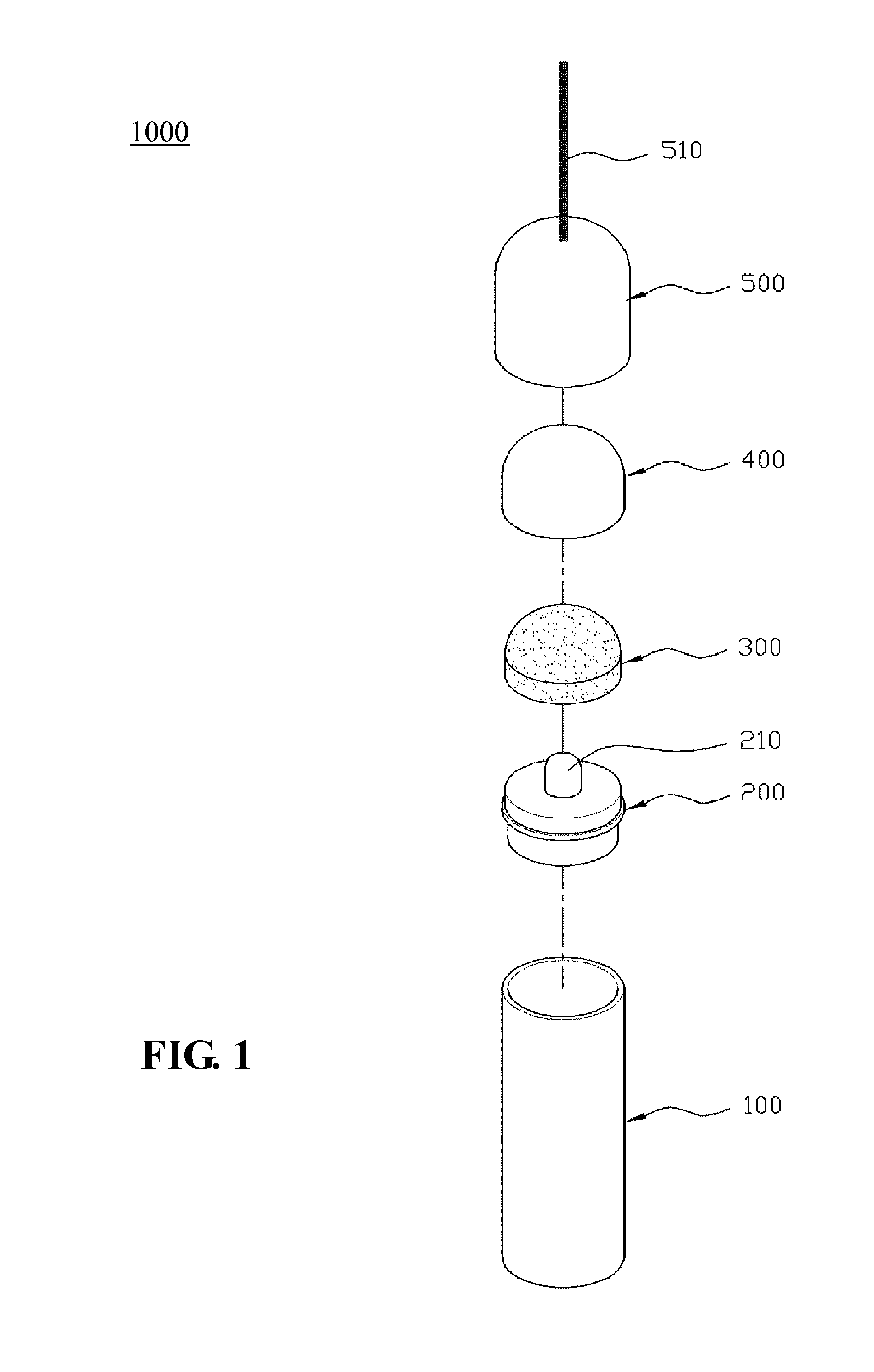
[0027]FIG. 1 is an exploded view of a stylus in accordance with an exemplary embodiment of the present disclosure.

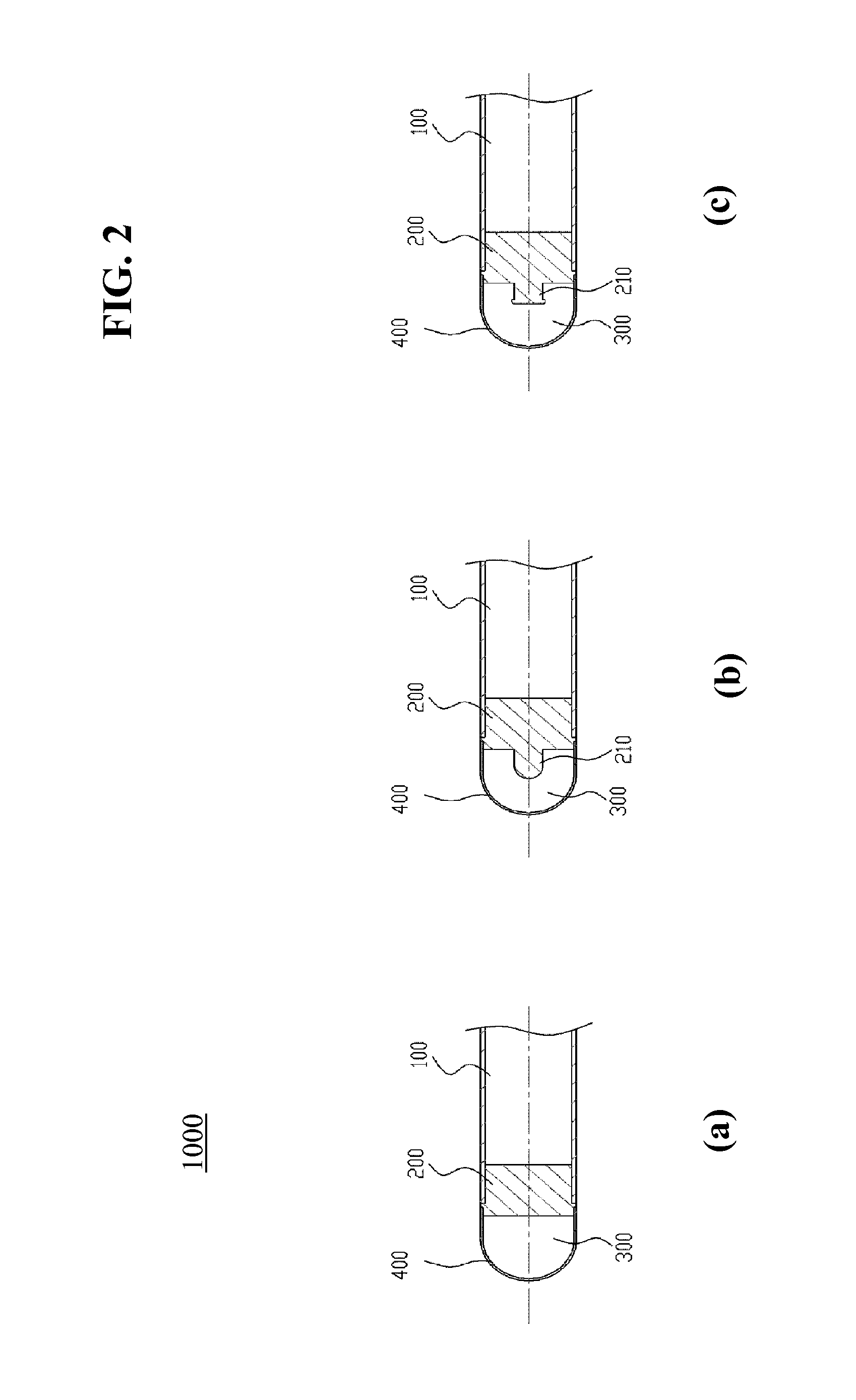
[0028]Referring to FIG. 1, a stylus 1000 according to an exemplary embodiment is configured to select one of plural pieces of content installed in advance in a communication terminal and to indicate an associated operation of the selected piece of content to be performed by touching the selected piece of content with the stylus. The stylus 1000 includes: a stick-shaped body 100, a pointer 200, a protrusion 210 on a top side of the pointer 200, a pen tip 300, a protective cap 400, a lid 500, and a securing strap 510 connected to an upper p...


PUM

PropertyMeasurementUnit
wt %aaaaaaaaaa
wt %aaaaaaaaaa
wt %aaaaaaaaaa

Abstract

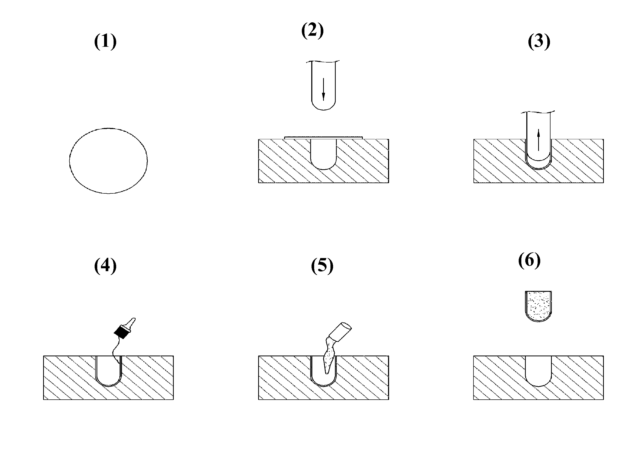
The present disclosure relates to a method of manufacturing a stylus pen configured to select one of plural pieces of content installed in advance in a communication terminal. Examples of the method comprise preparing a protective cap of a conductive fiber material by sequentially stacking nickel, copper and nickel on both sides of a polyester fiber by deposition coating, placing the protective cap on a mold, applying a bonding agent to an internal surface of the protective cap, and injecting a non-conductive liquid onto the internal upper portion of the protective cap.

Description

CROSS-REFERENCE TO RELATED APPLICATION[0001]This application is a divisional application of U.S. application Ser. No. 12 / 910,429 filed Oct. 22, 2010 which claims under 35 U.S.C. §119(a) the benefit of Korean Application No. 10-2010-0050647 filed May 28, 2010, the entire contents of which are incorporated herein by reference.BACKGROUND[0002]1. Technical Field[0003]The present disclosure relates to communication terminal techniques and, more particularly, to a stylus and a method of manufacturing the same, which may select one of plural pieces of content installed in advance in a communication terminal and allow an associated operation of the selected piece of content to be performed by touching the selected piece of content with the stylus.[0004]2. Description of the Related Art[0005]Generally, styluses include a pressure (or pressure-sensitive) stylus which is used to apply pressure to a touch screen such that an indicated position can be recognized by the touch screen, and a capaci...

Claims


Application Information

Patent Timeline
Patent Type & Authority Applications(United States)
IPC IPC(8): B29C70/68G06F3/033G06F3/0354
CPCG06F3/03545
Inventor NO, JONG WOONGKIM, DONGSIK
Owner XG SOLUTIONS
Learn More