
Mobile, climbing robotic system to perform remote welds on ferrous materials

a robotic system and remote welding technology, applied in the direction of soldering equipment, manufacturing tools, auxillary welding devices, etc., can solve the problems of limited use, difficult access to many portions of a large structure, and the requirement to pre-install the mechanical guide, etc., to achieve the effect of high payload to weight ratio of the vehicle and effective us

Inactive Publication Date: 2012-05-10
BEARD JAMES +2
View PDF36 Cites 29 Cited by
  • Summary
  • Abstract
  • Description
  • Claims
  • Application Information

AI Technical Summary

Benefits of technology

[0017]The invention described in this document creates a mobile welding platform capable of climbing all positions, flat, inverted and upside down positions while carrying and manipulating welding or other manufacturing tools. This invention allows a welding operator to perform a weld in a remote fashion in a variety of positions including flat surfaces, inverted surfaces horizontal or vertical, butt welds, lap welds and fillet welds. The invention allows the weld operations to occur surfaces that are not uniform, and provides a high payload to weight ratio of the vehicle by effective use of the adhering members through optimized load distribution.
[0019]1) The invention defines a prescribed magnetic field created by the permanent magnet tracks allowing adaptation with all welding type equipment, particularly welding processes that are most sensitive to external magnetic field (for example pulsed-arc GMAW type weld magnetic). This also allows the torch to be placed in many locations around the mobile platform, and it allows compact design, fit into compact areas by allowing the torch to be near magnetic tracks.
[0020]2) The welding platform of this invention integrates a multi-link suspension apparatus that distributes climbing loads to maximize the system payload to weight ratio.
[0022]4) The invention system contains a torch manipulator that is independently suspended from the tractor. Thus it isolates undesirable motions in the tractor from the torch. This lowers the control requirements on the tractor, allowing it to be small and control only the torch component. This keeps high resolution control components small, reduced mass, reduced dynamic control authority needed. This reduces the size and cost of the torch manipulator.

Problems solved by technology

However, there remain a number of systems that exist at a size, scale or location that do not permit traditional methods of automated welding.
This approach has several difficulties that generally limit its use: 1) it requires significant capital investment to design and install such a system, which affects the entire manufacture process, 2) This facility is at a fixed location and 3) it is difficult to access many portions of a large structure when assembly begins on a large system.
The primary difficulty with these systems lies in the requirement to pre-install the mechanical guide or track.
Further, the pre-installation process may limit the flexibility of the process in manufacturing; it generally is not feasible to leave the track installed for multiple manufacturing operations.
However, these carriages in general have a few key disadvantages, such as loss of holding strength from the magnets on non-flat surfaces, inability to adapt to curved surfaces or protrusions (for example weld seams) on a generally flat surface, and localization of the holding forces on to a small number of the adhering members when multiple magnetic adhering members are used.
These disadvantages have limited their widespread use of mobile welding carriages in automating welding operations in out of position welds.
The magnetic wheel systems are affixed to a rigid carriage, which will cause some of the wheels, when four or more wheels are used, to detach when operating on non-flat or non-uniform surfaces causing degradation in holding power.
The magnetic wheel systems are affixed to a frame which will cause some of the wheels, when four or more wheels are used, to detach when operating on non-flat or non-uniform surfaces causing degradation in holding power.
However, under equilibrium the loads are transferred according to the relative compliance of the carriage frame and wheel axle system and in general will be localized to a small number of the magnetic wheels causing degradation in holding power.
However, these systems tend to either place the magnets on a track without a track guide or mechanism between the end wheels (for example U.S. Pat. No. 5,884,642 or Shen and Shen, 2005) and rely on tension in the track to transfer climbing forces to the adhering members, or on a track with a rigid track guide limiting the ability to conform to a non-uniform climbing surfaces (for example U.S. Pat. No. 5,487,440, Kim et al., 2008) or a guide that has some flexibility but for purposes of pushing in a single direction on the track to make contact with the climbing surface (for example U.S. Pat. No. 4,789,037).
When climbing the loads required to maintain equilibrium are transferred to the adhering members according to the relative compliance of the carriage frame and endless track system and in general will be localized to a small number of the adhering members causing degradation in holding power.
This localizes the climbing forces on the magnets lying on the outer ends of the track contact region and degrades the payload capacity of the operating system.
This variable pitch results in a non-uniform velocity ratio between the drive wheel or sprocket rotation and translation of the vehicle over the climbing surface.
This is a problem in manufacturing operations such as welding where precise, controlled travel speeds are required to maintain the quality of the weld process.
However, these devices contain several limitations that have restricted their widespread use in manufacturing, including the ability to climb over surfaces with variations or regularities, efficient use of the adhering members by distributing the climbing load in an improved fashion, and maintaining uniform, stabilized motion of the weld torch.

Method used


Image

  • Mobile, climbing robotic system to perform remote welds on ferrous materials
  • Mobile, climbing robotic system to perform remote welds on ferrous materials
  • Mobile, climbing robotic system to perform remote welds on ferrous materials

Examples


Embodiment Construction

[0047]Detailed descriptions of the preferred embodiment are provided herein. It is to be understood, however, that the present invention may be embodied in various forms. Therefore, specific details disclosed herein are not to be interpreted as limiting, but rather as a basis for the claims and as a representative basis for teaching one skilled in the art to employ the present invention in virtually any appropriately detailed system, structure or manner.

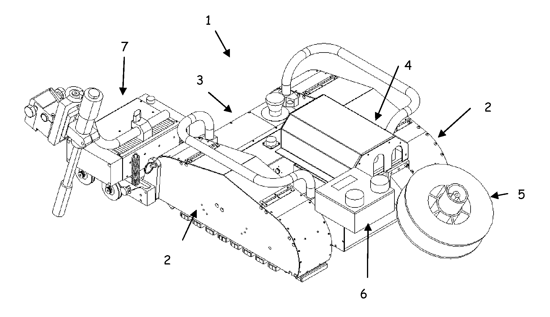
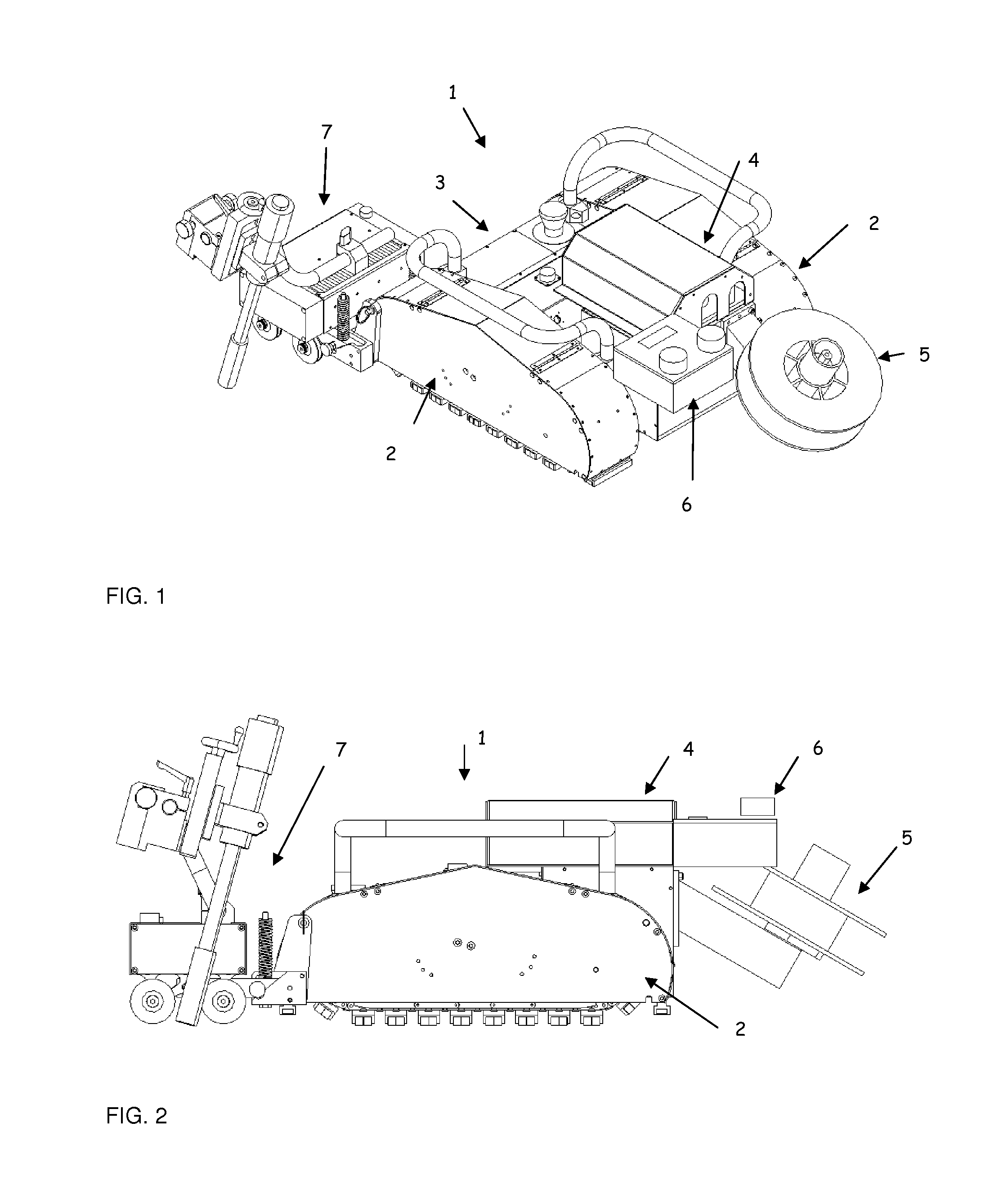
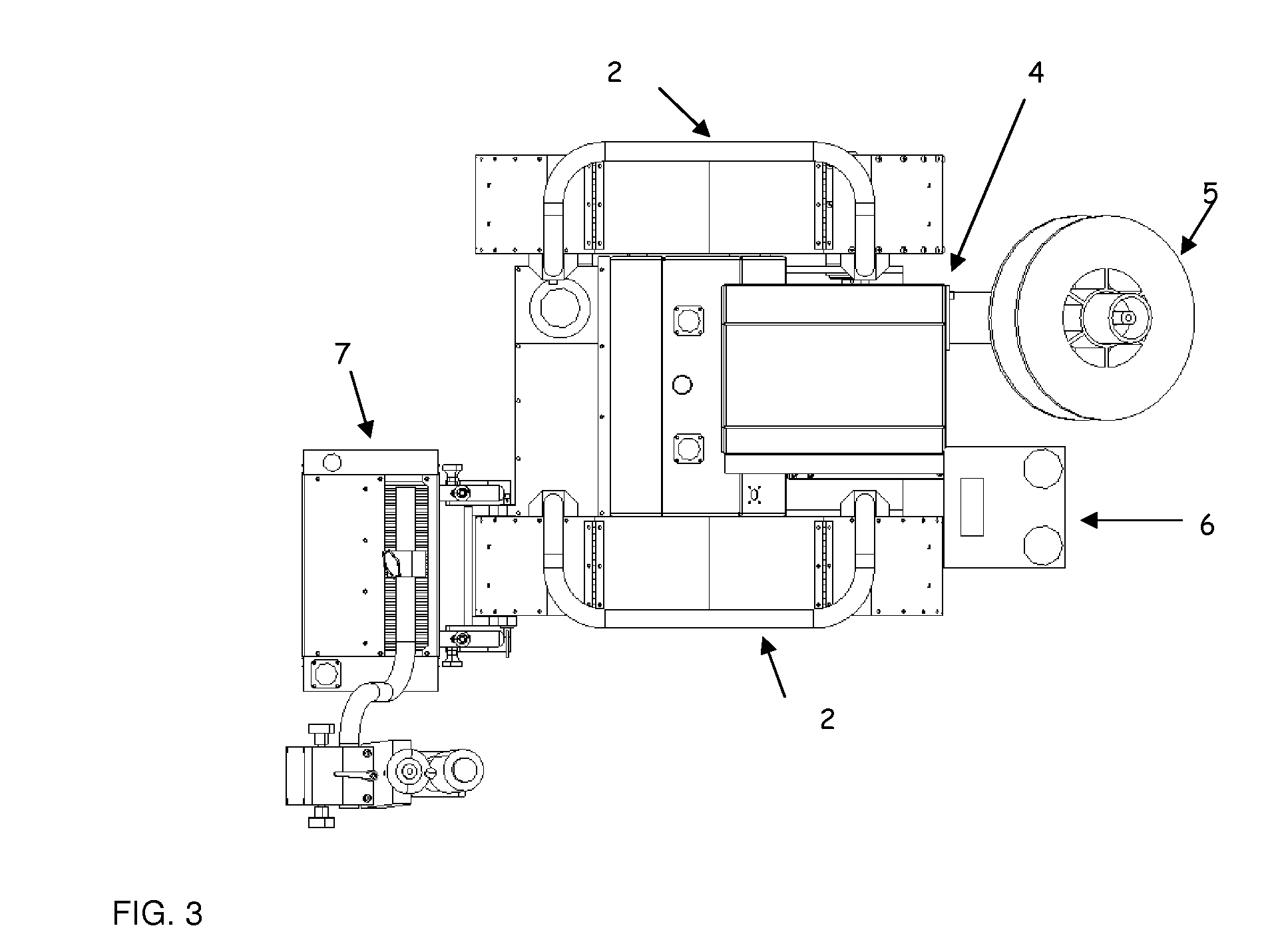
[0048]The mobile endless track welding vehicle (1) is illustrated in FIGS. 1, 2, and 3 here the endless track units (2) are connected to a chassis (3). The weld support tools can also be attached to the chassis and may consist of a commercial wire feed unit (4), spool of welding wire (5) and welding feed and / or power system controls (6). The universally-mounted torch manipulator (7) is attached to one of multiple mounting locations on a track unit or chassis. The track units are geometrically similar and symmetric; one is shown in FI...


PUM

PropertyMeasurementUnit
Pressureaaaaaaaaaa
Forceaaaaaaaaaa
Magnetic fieldaaaaaaaaaa

Abstract

An endless-track type mobile climbing vehicle containing a suspension apparatus and tool manipulator to perform trackless, guide-free welding in all positions or other manufacturing tasks. The invention can conform to a wide range of surface irregularities while maintaining contact between the track and adhering members and uniformly distributing the climbing loads on the adhering members giving the system a high payload to weight ratio. The vehicle with tool manipulator provides all necessary tool motion and stabilizes tool motion for tasks with strict requirements such as welding. The invention allows an operator to supervise and control the weld process through a controller. The invention allows the operator to specify weld motion control parameters for five axes and provides closed loop motion control to track the settings input by the welding operator. The invention also provides closed-loop tracking control to maintain the position of the robot along the longitudinal weld seam.

Description

CROSS REFERENCE TO RELATED APPLICATIONS [0001]This application claims the priority of U.S. Provisional Application Ser. No. 61 / 456,416 entitled “Mobile, climbing robotic system to perform remote welds on ferrous structures” filed on Nov. 8, 2010, the entire contents and substance of which are hereby incorporated in total by reference.STATEMENT REGARDING FEDERALLY SPONSORED RESEARCH OR DEVELOPMENT [0002]Not ApplicableDESCRIPTION OF ATTACHED APPENDIX [0003]Not ApplicableBACKGROUND OF THE INVENTION[0004]Welding is a common joining technique for many materials and the most common bonding method for metals. Welding is a commonly automated manufacturing technique for many metal-based products. However, there remain a number of systems that exist at a size, scale or location that do not permit traditional methods of automated welding. Methods that have been proposed, developed and or implemented to provide some level of mechanization or automation to these types of systems might be placed ...

Claims


Application Information

Patent Timeline
IPC IPC(8): B23K9/32
CPCB23K9/173B23K37/0241B23K2203/04B23K37/0282B23K37/0264B23K2101/006B23K2103/04
Inventor BEARD, JAMESCANFIELD, STEPHENGLOVSKY, STEVEN
Owner BEARD JAMES
Learn More