
Magnetic sensor device, method of operating such a device and sample

a magnetic sensor and sensor technology, applied in the field of sensor devices, can solve the problems of erroneous measurement signals, deformation of the first part of the binding couple of the biomolecule attached to the sensor surface, and unreliable diagnostic results, so as to avoid or at least reduce the unnecessary rejection of such an apparatus, facilitate the quality assessment of the sensor device, and avoid the effect of unnecessary rejection of the sensor devi

Active Publication Date: 2012-05-03
SIEMENS HEALTHINEERS NEDERLAND BV
View PDF6 Cites 5 Cited by
  • Summary
  • Abstract
  • Description
  • Claims
  • Application Information

AI Technical Summary

Benefits of technology

"The present invention provides a sensor device for detecting the presence of a target molecule in a sample. The sensor device includes a measurement surface region carrying a first moiety for selectively binding to a first further moiety comprising a detectable label. The sensor device also includes a reference surface region carrying a second further moiety for selectively binding to a second moiety. The sensor device generates a first detection signal from the detection of the label in the first further moiety and a second detection signal from the second further moiety. The sensor device can verify the accuracy of the detection signal by comparing it to an expected value. The sensor device can detect the target molecule in a stationary sample and can be used in various applications such as in biomolecule assays and in sample preparation."

Problems solved by technology

As is the case with any type of assay-based device, misuse of the device can produce unreliable diagnostic results.
For instance, the biomolecules that are attached to the sensor surface as the first part of the binding couple can degrade when the sensor device is exposed to adverse environmental conditions or has been otherwise damaged.
Also, the correct procedure for preparing the sample and / or applying the sample may not be followed, e.g. the sample is incorrectly prepared, the wrong amount of sample is added and so on, which also can cause erroneous measurement signals.

Method used


Image

  • Magnetic sensor device, method of operating such a device and sample
  • Magnetic sensor device, method of operating such a device and sample
  • Magnetic sensor device, method of operating such a device and sample

Examples


Embodiment Construction

[0037]Embodiments of the invention are described in more detail and by way of non-limiting examples with reference to the accompanying drawings, wherein

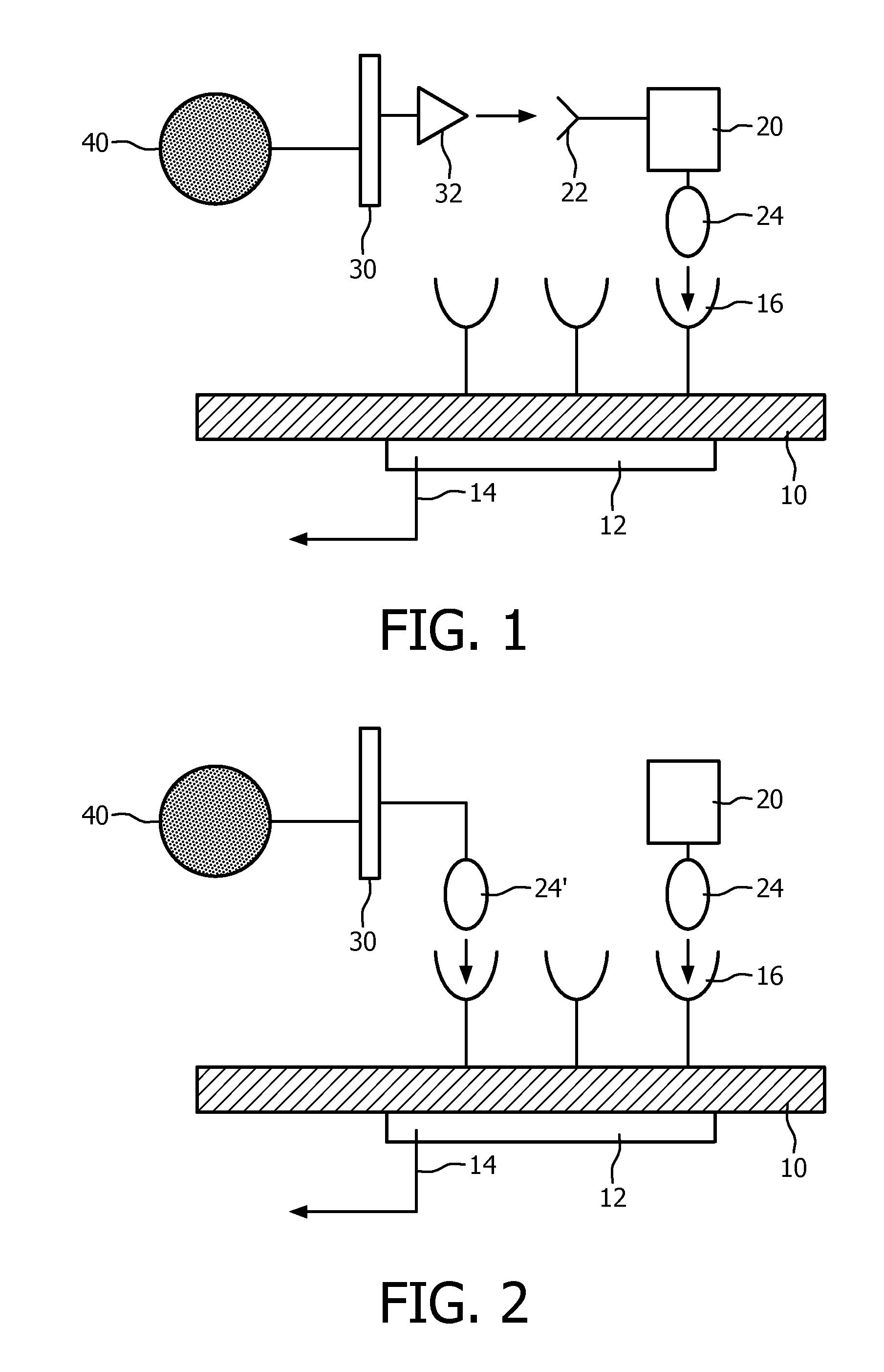
[0038]FIG. 1 schematically depicts a sandwich assay-based sensor device;

[0039]FIG. 2 schematically depicts a competitive assay-based sensor device;

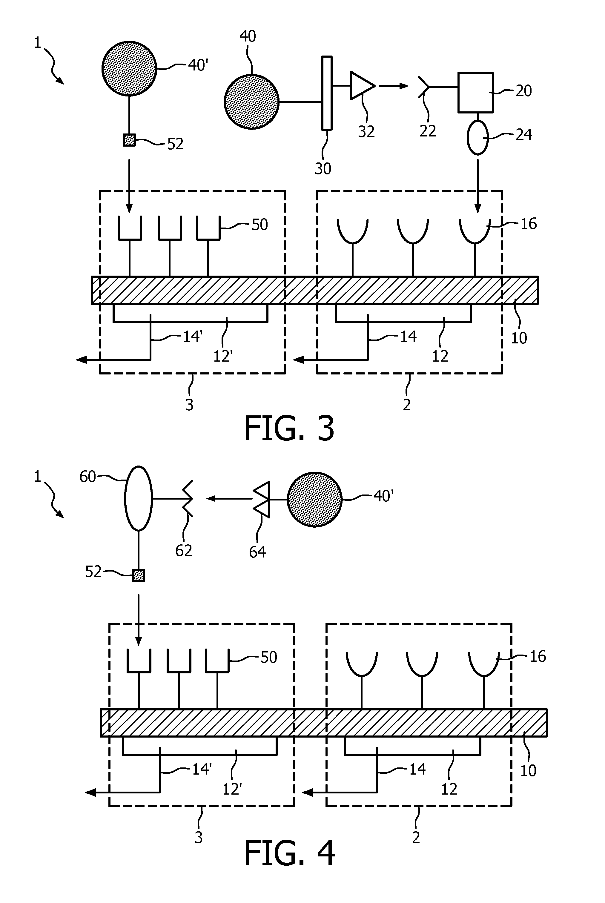
[0040]FIG. 3 schematically depicts an assay-based sensor device in accordance with an embodiment of the present invention;

[0041]FIG. 4 schematically depicts an assay-based sensor device in accordance with an another embodiment of the present invention;

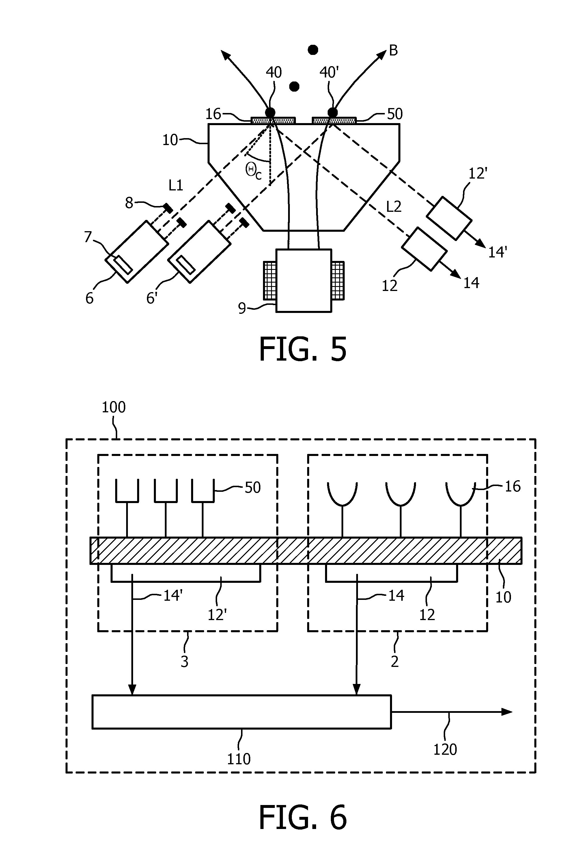
[0042]FIG. 5 schematically depicts a preferred embodiment of an assay-based sensor device;

[0043]FIG. 6 schematically depicts an apparatus in accordance with an embodiment of the present invention;

[0044]FIG. 7 depicts a flow chart of an aspect of a method in accordance with an embodiment of the present invention;

[0045]FIG. 8 depicts a flow chart of another aspect of a method in accordance with an embodiment of the present invention; and

[0046]F...


PUM

PropertyMeasurementUnit
reaction ratesaaaaaaaaaa
diameteraaaaaaaaaa
affinityaaaaaaaaaa

Abstract

A sensor device (1) for detecting the presence of a target molecule (20) in a sample, is disclosed. The sensor device comprises a measurement sensor (2) comprising a first moiety (16) for forming a binding couple with a first further moiety comprising the target molecule (20) and a detectable label (40) and a reference sensor (3) comprising a second moiety (50) for forming a further binding couple with a second further moiety comprising a further detectable label (40′). The sensor device is adapted to generate a first detection signal (14) from the detection of the detectable label (40) in the first further moiety bound to the first moiety (16) and to generate a second detection signal (14′) from the detection of the further detectable label (40′) in the second further moiety bound to the second moiety (50), wherein at least during operation of the sensor device the second further moiety is expected to be present in a predefined amount such that the value of the second detection signal (14′) falls within an expected signal value window when the binding reaction of the second further moiety to the second moiety takes place as expected. An apparatus comprising such a sensor device, methods of operating the sensor device and apparatus and a sample for use with the sensor device are also disclosed.

Description

FIELD OF THE INVENTION[0001]The present invention relates to a sensor device for detecting the presence of a target molecule in a sample, comprising a measurement surface region carrying a first moiety for selectively binding a first further moiety comprising the target molecule and a detectable label and being adapted to generate a first detection signal from the detectable label of the further moiety bound to the first moiety.[0002]The present invention further relates to an apparatus comprising such a sensor device.[0003]The present invention yet further relates to a method of operating such a sensor device.[0004]The present invention even further relates to a sample for use with such a sensor device.BACKGROUND OF THE INVENTION[0005]In the field of medial diagnostics, assay-based sensor devices are rapidly gaining popularity because of the prospect of being able to accurately determine the presence and concentration of a wide variety of analytes in samples of interest. To this en...

Claims


Application Information

Patent Timeline
Patent Type & Authority Applications(United States)
IPC IPC(8): G01N33/566G01N30/00
CPCG01N27/745G01N33/54326G01N33/54366G01N33/54386G01N21/552
Inventor DITTMER, WENDY UYENDE THEIJE, FEMKE KARINAIMMINK, ALBERT HENDRIK JANNIEUWENHUIS, JEROEN HANSVAN LANKVELT, PETRUS JOHANNES WILHELMUS
Owner SIEMENS HEALTHINEERS NEDERLAND BV
Learn More