
Built-in type antenna displayer

a displayer and antenna technology, applied in the field of displayers, can solve the problems of increasing the price of notebook computers with wireless communication capabilities, affecting the appearance of notebook computers, so as to achieve the effect of increasing the thickness of notebook computers

Inactive Publication Date: 2012-05-03
KAO PEN JUNG
View PDF7 Cites 6 Cited by
  • Summary
  • Abstract
  • Description
  • Claims
  • Application Information

AI Technical Summary

Benefits of technology

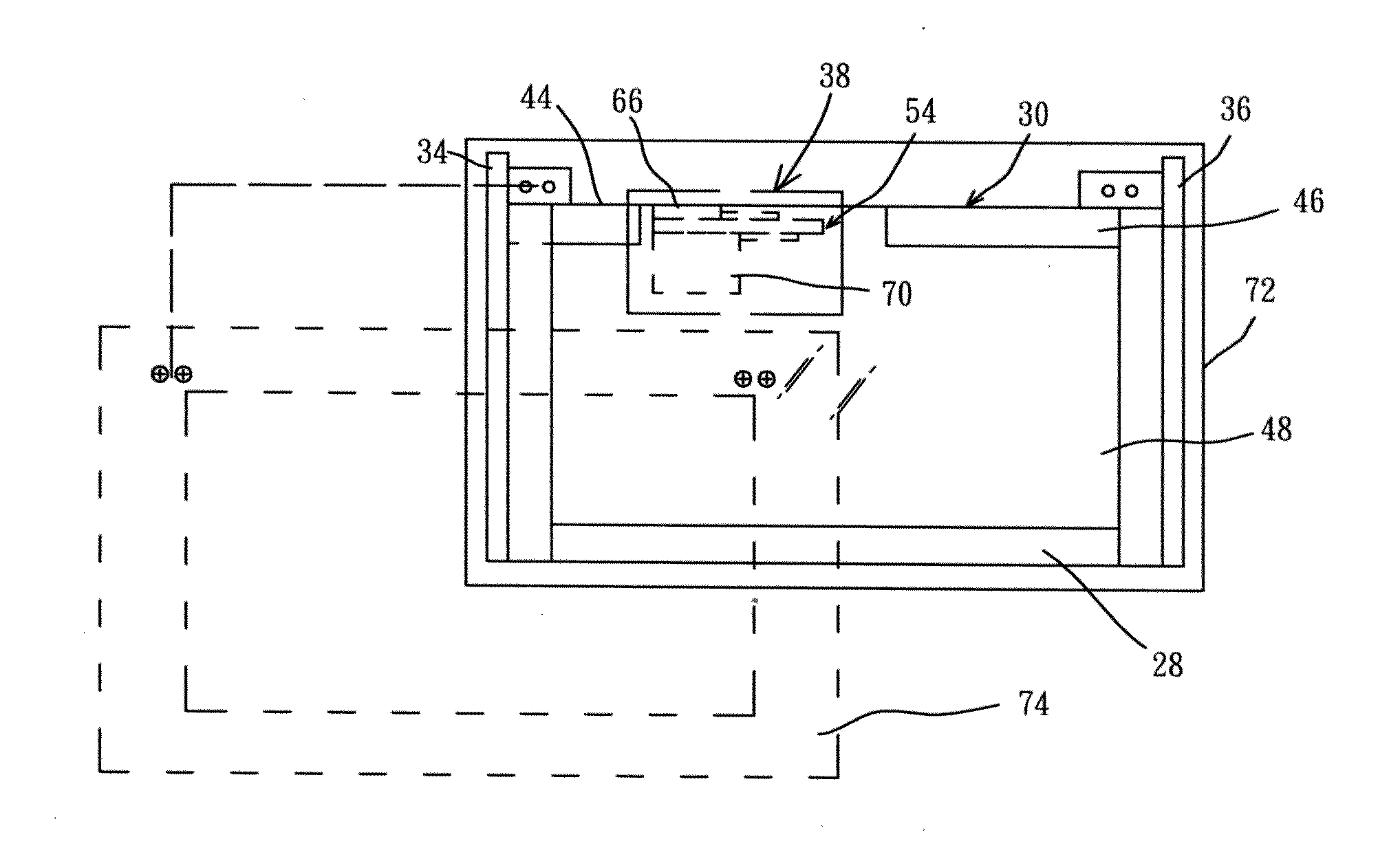
[0010]A major objective of the present invention is to provide a built-in type antenna displayer, that is formed on a metal frame of a displayer of a non-coplanar antenna, so as to solve the problem of the prior art of the additional installation cost for the antenna and the additional space occupied by the width, length and height of the antenna.
[0011]Another objective of the present invention is to provide a built-in type antenna displayer, that could avoid placing the signal feed-in point of the antenna at the front side or back side of the display panel, since that would have the shortcomings of increasing the thickness of the notebook computer, and also causing the breaking of the welding points of the coaxial cable for being pressed by outside force, or the breaking of the display panel for being pressed by the coaxial cable.

Problems solved by technology

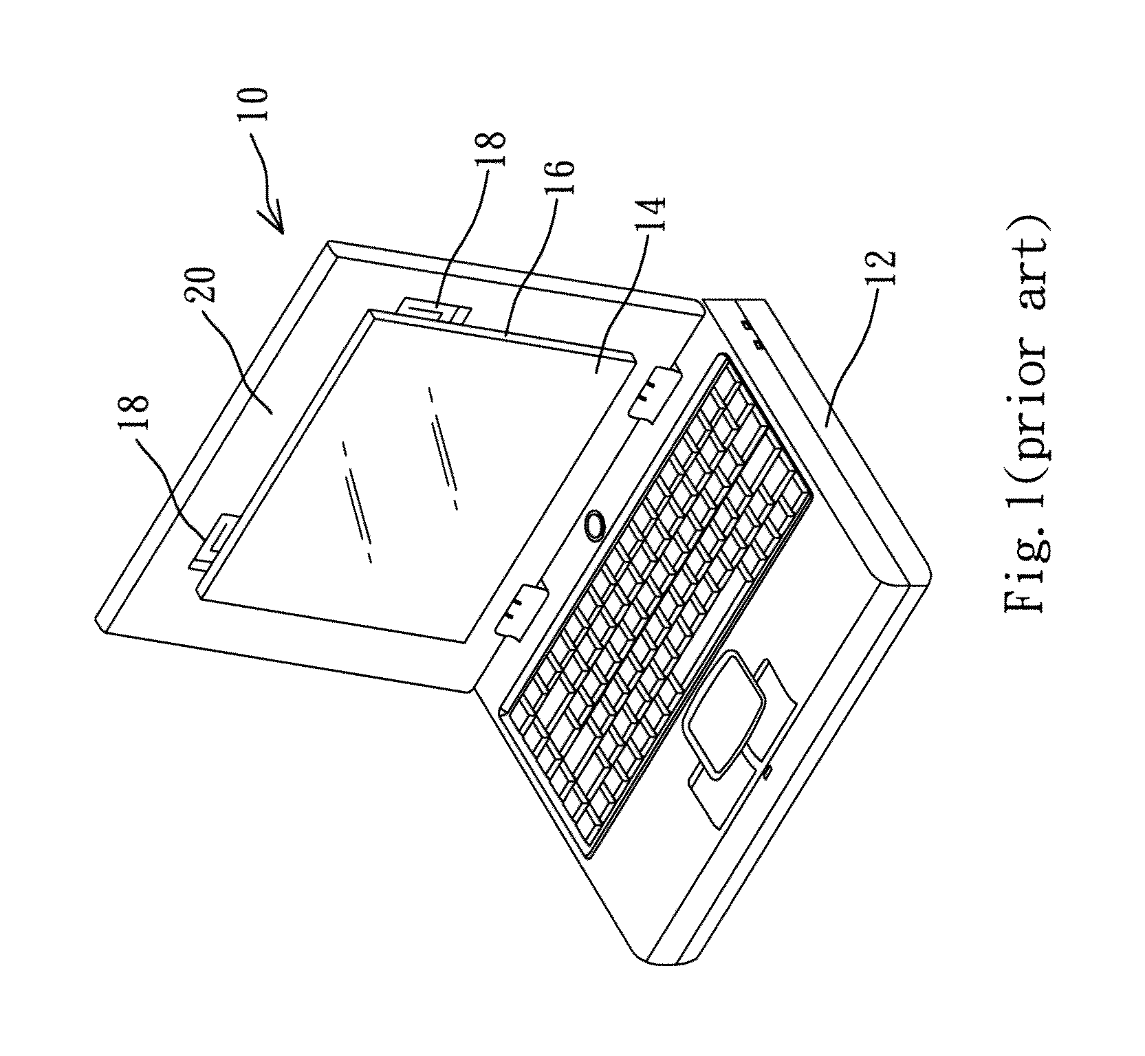
However, the cost of this kind of outside antenna is rather high, hereby raising the price of the notebook computer having wireless communication capabilities.
Moreover, since this type of outside antenna is provided on a displayer in a protrusion manner, and except for the housing of the antenna, it lacks outside cover and protection for the main body of antenna, therefore, after long period of usage, this type of outside antenna is liable to be damaged due to improper handling of the user, thus making the notebook computer not being able to realize wireless data communications.
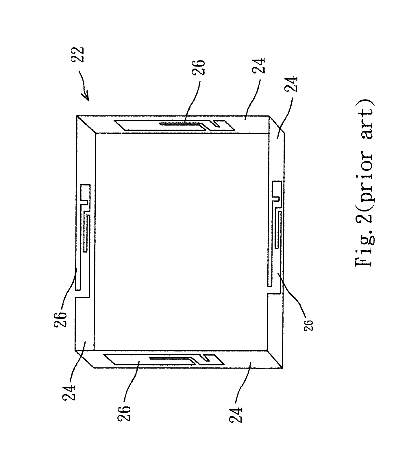
However, in this structure, thicker space is required to avoid interference of components.
Yet under the demand of thin-profile of notebook computer, in case the display panel of thickness less than 4 mm is utilized, then a wideband WLAN triple band antenna can not be realized due to insufficient thickness.
Therefore, at present, the design and structure of the antenna displayer are not quite satisfactory, and it has much room for further improvement.

Method used


Image

  • Built-in type antenna displayer
  • Built-in type antenna displayer
  • Built-in type antenna displayer

Examples


Embodiment Construction

[0026]The purpose, construction, features, functions and advantages of the present invention can be appreciated and understood more thoroughly through the following detailed description with reference to the attached drawings.

[0027]In view of the present trend of light-weight, thin-profile, and compact-size of the notebook computer, and in consideration of resonance frequency deviation of the antenna, as caused by the size differences of metal frame and metal bracket, or the difference of dielectric coefficients of display panel and the plastic cover plate, the present invention adopts a special design of a wide bandwidth antenna, such that it can not only be adapted to use in a thin-profile displayer, but it can also avoid the adverse influence of different ways of fixing metal brackets.

[0028]Refer to FIGS. 3 and 4 at the same time for an exploded view and a schematic diagram respectively of the built-in type antenna displayer according to the present invention. As shown in FIGS. 3...


PUM


Abstract

A built-in type antenna displayer, formed by at least an antenna integrally on a metal frame, and said metal frame is fixed onto an outer edge of a display panel, on said outer edge of said display panel is provided with an installation surface. Said metal frame is provided with a first sidewall, and a second sidewall connected vertically to said first sidewall, so as to form an L-shape structure. On said first sidewall is formed a signal feed-in terminal and a ground terminal, and that are both located on said installation surface. On said second sidewall is provided with a resonance radiator, that is connected vertically to said installation surface, such that said resonance radiator is connected vertically to said signal feed-in terminal to form a non-coplanar structure having a WLAN triple band antenna.

Description

BACKGROUND OF THE INVENTION[0001]1. Field of the Invention[0002]The present invention relates to a displayer, and in particular to a non-coplanar type Wireless Local Area Network (WLAN) triple band antenna structure formed integrally on a metal frame of a displayer.[0003]2. The Prior Arts[0004]Along with the progress and development of computer technology, notebook computer is now very popular and widely utilized, and it has become an indispensable part in the work and life of people of the modern age. Therefore, the functions provided by the notebook computer and its convenience in usage are essential to the efficiency of carrying on our daily life. In addition, with the advent of the age of wireless network communications, notebook computer is now equipped with antenna in achieving wireless communications. In the design and arrangement of an antenna, it must fulfill all the users' requirements of light-weight, thin-profile, and compact-size of a notebook computer at the same time,...

Claims


Application Information

Patent Timeline
Patent Type & Authority Applications(United States)
IPC IPC(8): H05K7/00H01Q5/10
CPCG06F1/1698H01Q1/2266H01Q21/28H01Q5/364
Inventor KAO, PEN-JUNG
Owner KAO PEN JUNG
Learn More