Liquid crystal display
a liquid crystal display and vertical alignment technology, applied in non-linear optics, instruments, optics, etc., can solve the problems of increasing consumption current, increasing load of drive units, and affecting so as to improve the display quality of vertical alignment
- Summary
- Abstract
- Description
- Claims
- Application Information
AI Technical Summary
Benefits of technology
Problems solved by technology
Method used
Image

Examples
first embodiment
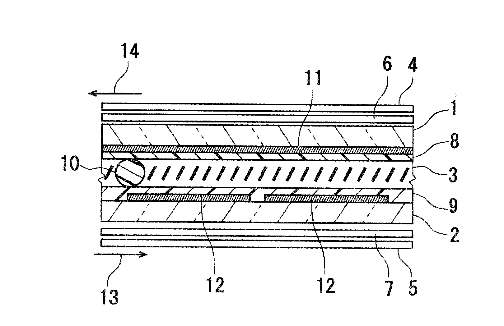
[0078]FIG. 1 is a schematic cross section showing the structure of the liquid crystal display device according to one embodiment of the present invention. The liquid crystal display device of this embodiment shown in FIG. 1 mainly comprises a first substrate 1 and a second substrate 2 placed opposite each other and a liquid crystal layer 3 provided between both substrates. A first polarizer 4 is disposed outside the first substrate 1, and a second polarizer 5 is disposed outside the second substrate 2. A first viewing angle compensator 6 is disposed between the first substrate 1 and the first polarizer 4, and a second viewing angle compensator 7 is disposed between the second substrate 2 and the second polarizer 5. The periphery of the liquid crystal layer 3 is sealed with a sealant which is not shown in FIG. 1. The structure of the liquid crystal display device is now explained in further detail.
[0079]The first substrate 1 and the second substrate 2 are respectively, for example, t...
second embodiment
[0115]In the second embodiment, both the improvement of display quality and the reduction of frame frequency are achieved by causing the electrode edges of the respective electrode to be a broken curve shape. Some specific structures are illustrated below. Note that the basic configuration of the liquid crystal display device is common with the foregoing first embodiment (refer to FIG. 1).
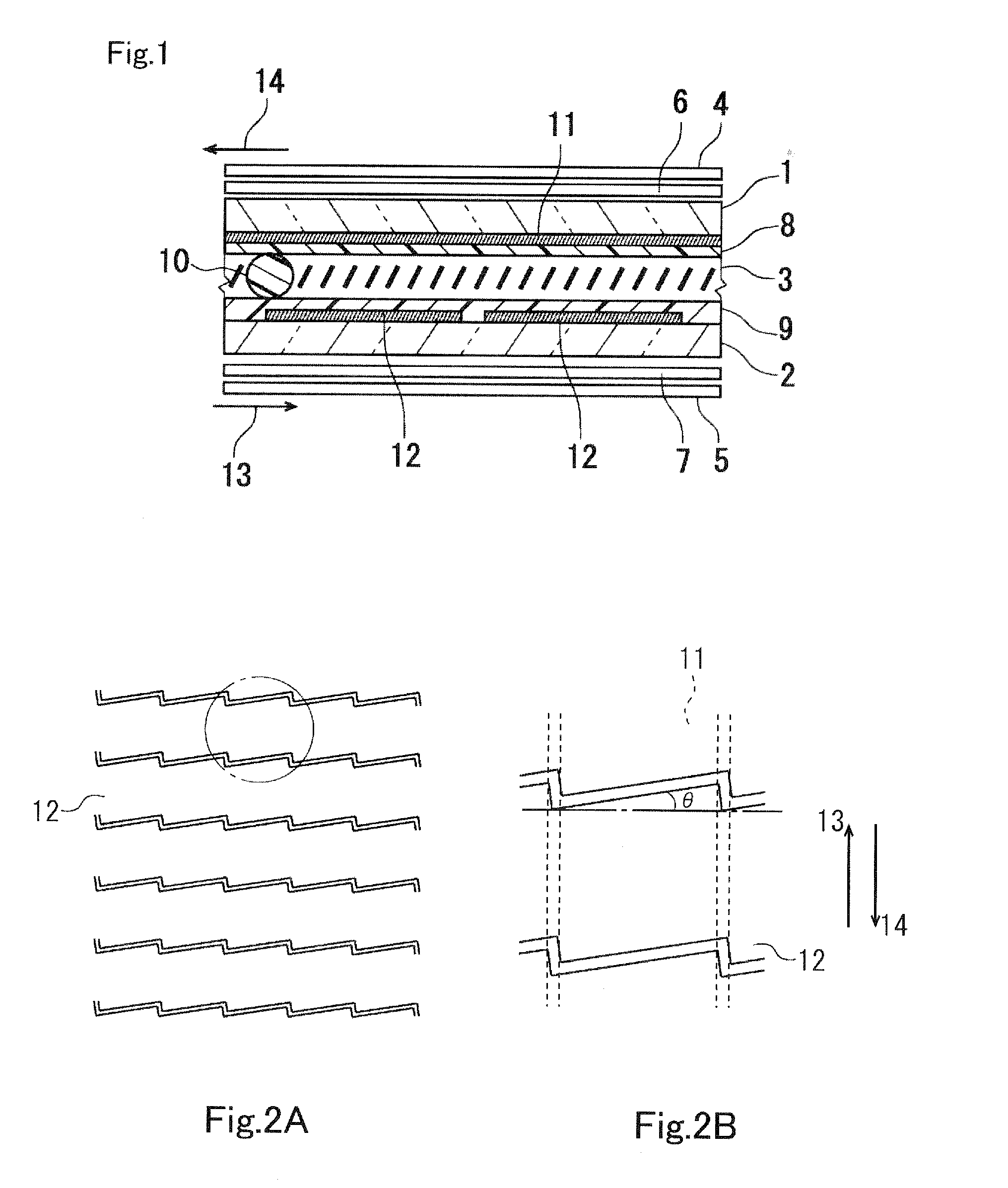
[0116]FIGS. 15A and 15B are schematic plan views showing other example of the electrode structure. As shown in FIG. 15A, the electrode edge of the respective first electrodes 11 extending in the longitudinal direction in the diagram is formed in a saw teeth shape, and one pitch of the saw teeth basically coincides with the electrode width of the respective second electrodes 12. Moreover, the electrode edges of the respective second electrodes 12 are formed in the same saw teeth shape as those shown in FIGS. 7A and 7B of the foregoing first embodiment, and one pitch of the saw teeth is set to be app...
third embodiment
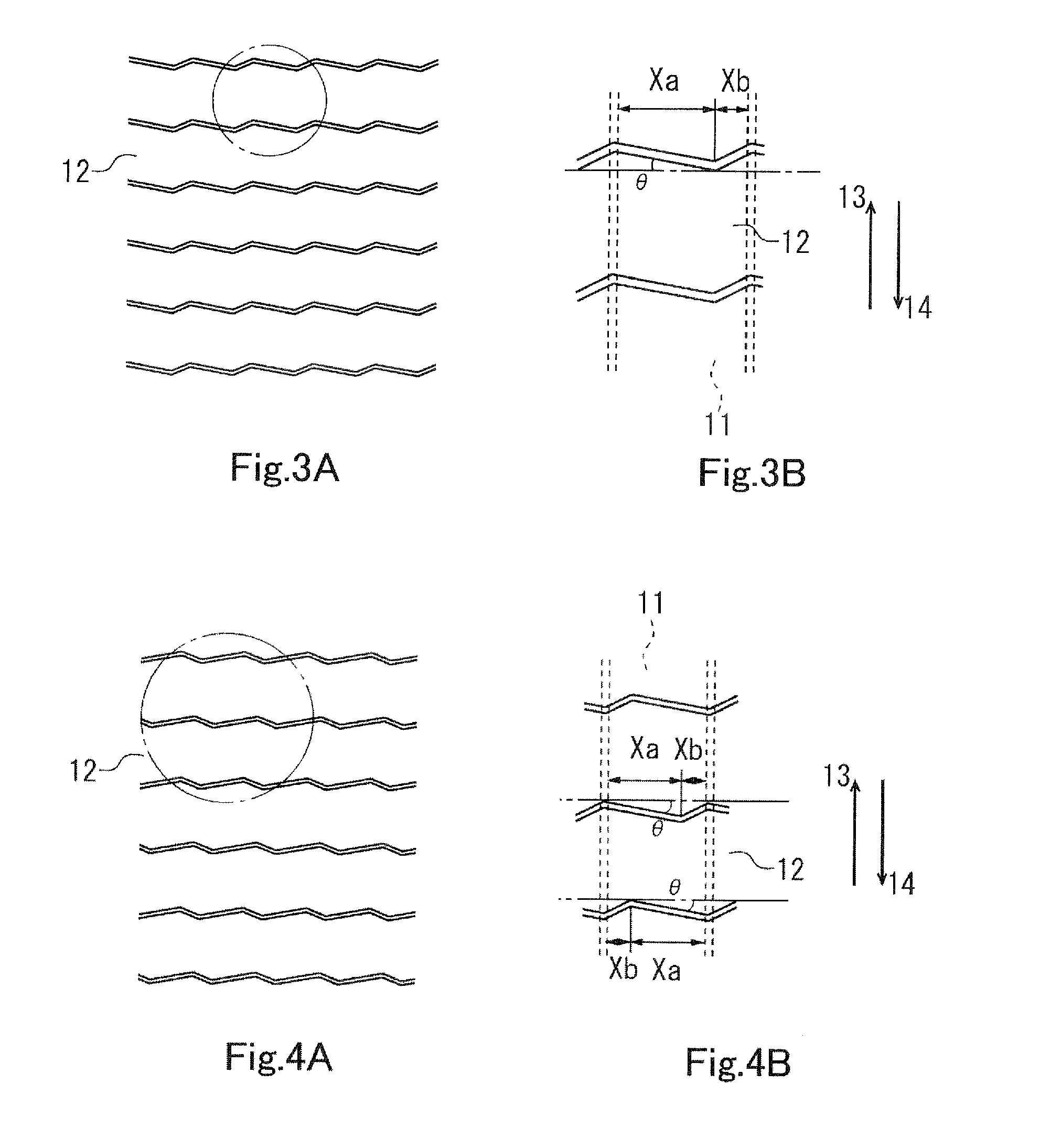
[0127]In the third embodiment, by causing the electrode edge of the respective second electrodes 12 to be a broken curve shape including a line segment which obliquely crosses the extending direction (first direction) of the first electrode, a structure is achieved where the pixel edge of the portion that is demarcated by the electrode edge of the respective second electrodes 12 among the respective pixels and the directions 13, 14 of the respective alignment treatment are not orthogonal. Moreover, by providing rectangular openings to the respective first electrodes 11, the reduction of the frame frequency is sought. Some specific structures are illustrated below. Note that the basic configuration of the liquid crystal display device is common with the foregoing first embodiment (refer to FIG. 1).
[0128]The electrode structure of the second electrode in the third embodiment is common with the foregoing first embodiment. Specifically, the second electrode in the third embodiment has t...
PUM
 Abstract
Description
Claims
Application Information
 - R&D
- Intellectual Property
- Life Sciences
- Materials
- Tech Scout
- Unparalleled Data Quality
- Higher Quality Content
- 60% Fewer Hallucinations
Browse by: Latest US Patents, China's latest patents, Technical Efficacy Thesaurus, Application Domain, Technology Topic, Popular Technical Reports.
© 2025 PatSnap. All rights reserved.Legal|Privacy policy|Modern Slavery Act Transparency Statement|Sitemap|About US| Contact US: help@patsnap.com