Lock for locking a movable member to fixed member

a technology for locking movable parts and fixing parts, applied in the field of locks, can solve problems such as being unsuitable for the purposes of an embodimen

Inactive Publication Date: 2012-05-03
SHARTEL MARK W
View PDF42 Cites 7 Cited by
  • Summary
  • Abstract
  • Description
  • Claims
  • Application Information

AI Technical Summary

Benefits of technology

[0015]Thus, an object of an embodiment of the present invention is to provide a lock for locking a movable member to a fixed member, which avoids the disadvantages of the prior art.
[0016]Briefly stated, another object of an embodiment of the present invention is to provide a lock for locking a movable member to a fixed member, wherein the movable member has a recess, and wherein the fixed member has a threaded through bore. The lock includes a head, a stem, first locking apparatus, and an optional second locking apparatus. The head is for selective rotational resting in the recess in the movable member. The stem selectively movably depends from the head and is for selectively engaging in the threaded through bore in the fixed member. The first locking apparatus selectively prevents rotation of the head relative to the stem to thereby prevent rotation of the stem and withdrawal thereof from the threaded through bore in the fixed member to thereby selectively prevent removal of the lock from the fixed member. The second locking apparatus depends operatively from the stem, is operatively connected to the first locking apparatus, and is for selectively preventing retraction of the stem from the threaded through bore in the fixed member to thereby further selectively prevent removal of the lock from the fixed member.

Problems solved by technology

Furthermore, even though these innovations may be suitable for the specific individual purposes to which they address, however, they would not be suitable for the purposes of an embodiment of the present invention as heretofore described.

Method used


Image

  • Lock for locking a movable member to fixed member
  • Lock for locking a movable member to fixed member
  • Lock for locking a movable member to fixed member

Examples


Embodiment Construction

A. General

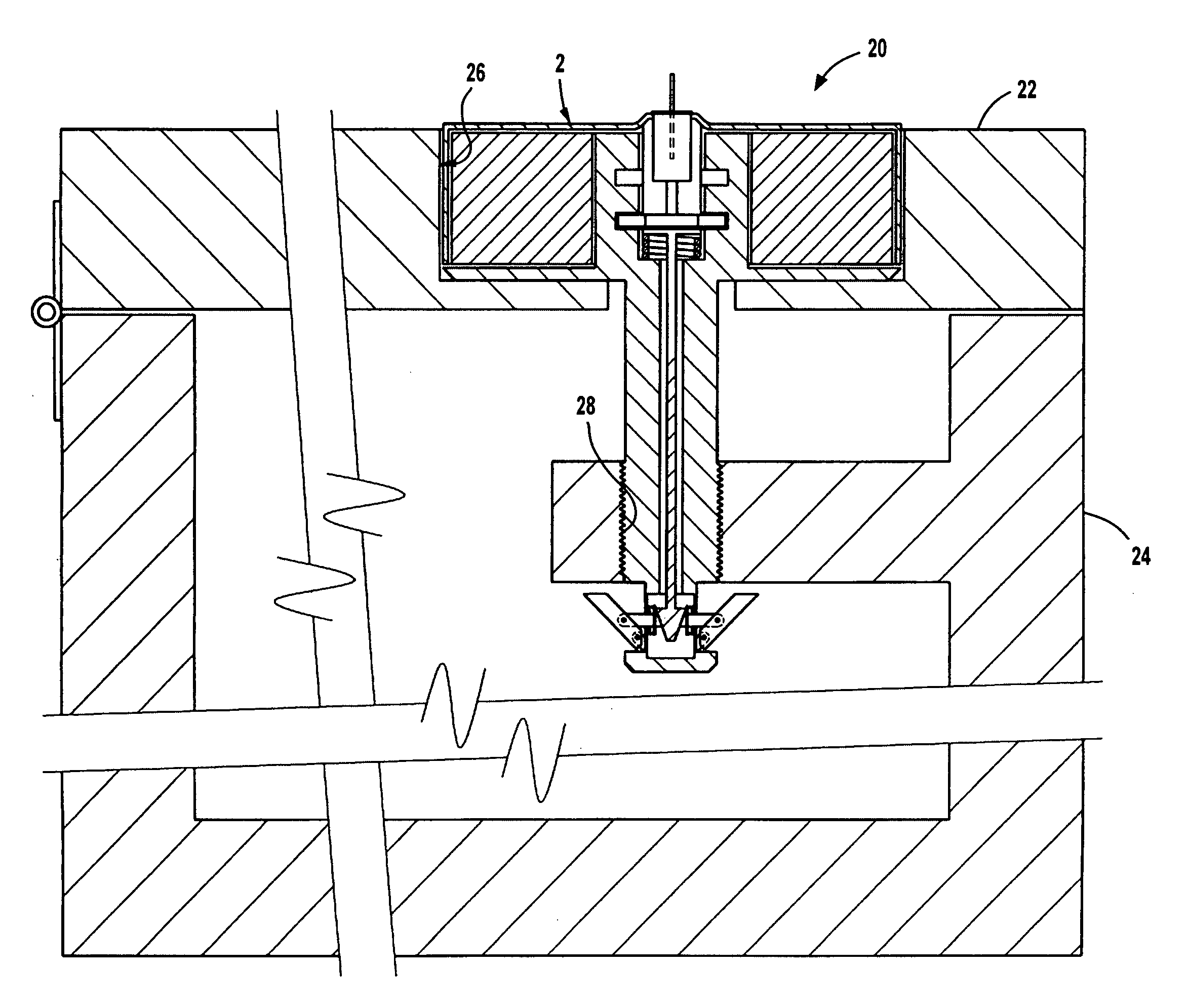
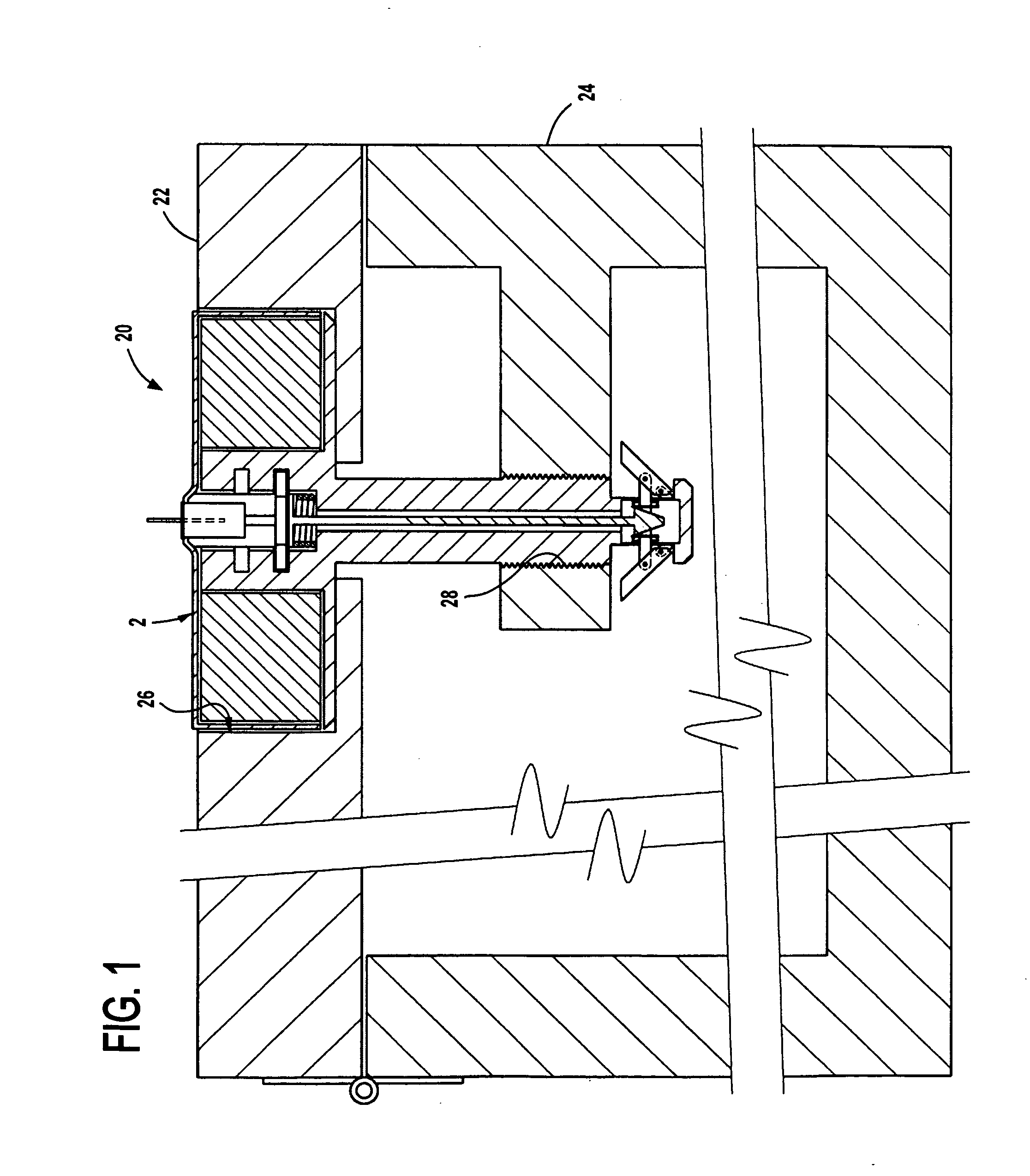
[0096]Referring now to the figures, in which like numerals indicate like parts, and particularly to FIG. 1, which is a diagrammatic cross sectional view of the lock of an embodiment of the present invention locking a movable member to a fixed member, the lock of an embodiment of the present invention is shown generally at 20 for locking a movable member 22 to a fixed member 24, wherein the movable member 22 has a recess 26 and the fixed member 24 has a threaded through bore 28.

B. Overall Configuration of the Lock 20

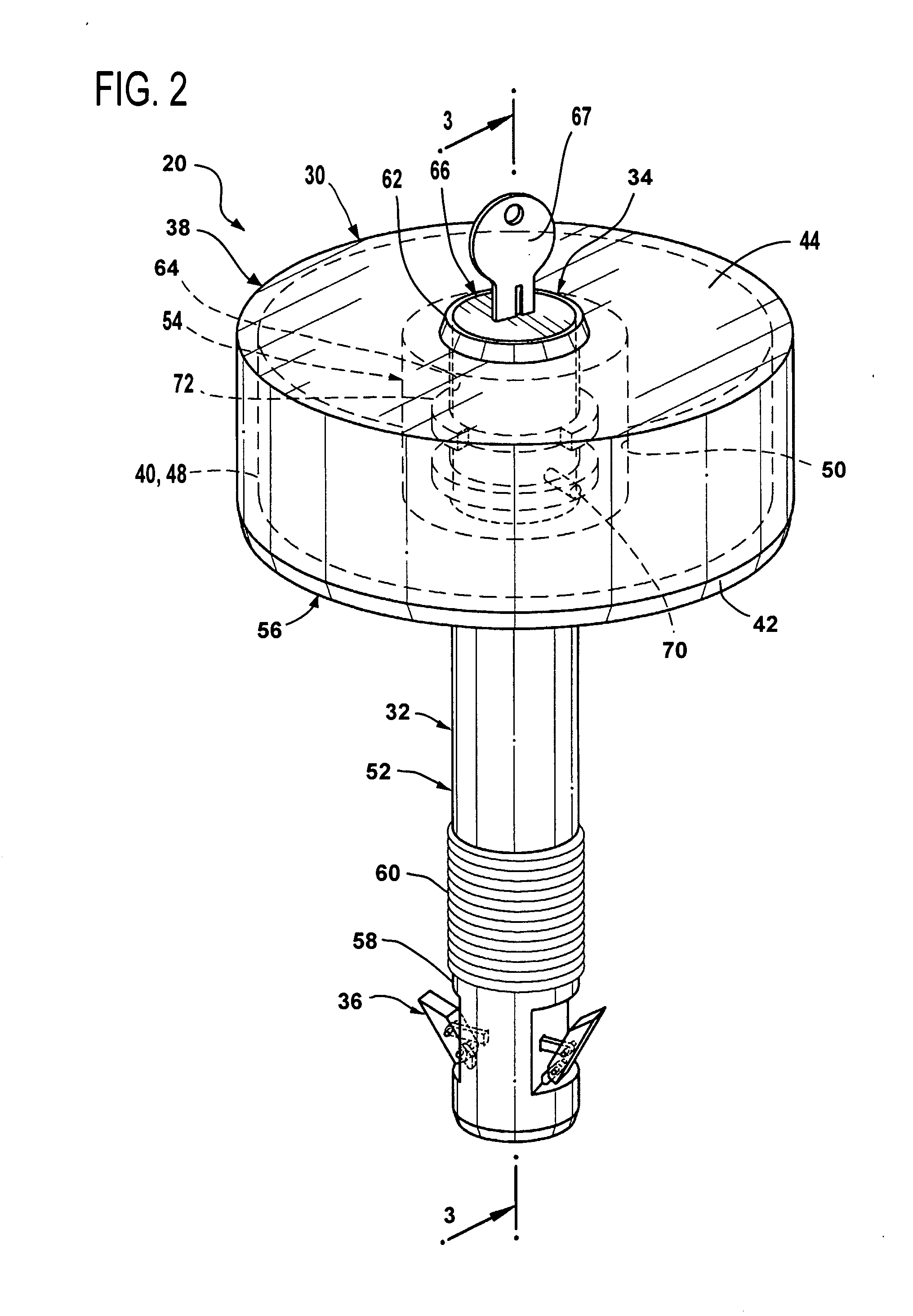
[0097]The overall configuration of the lock 20 can best be seen in FIGS. 2, 3, 4, and 5, which are, respectively, an enlarged diagrammatic perspective view of the lock of an embodiment of the present invention identified by ARROW 2 in FIG. 1, a diagrammatic cross sectional view taken along LINE 3-3 in FIG. 2, a reduced exploded diagrammatic prospective view of the lock of an embodiment of the present invention shown in FIG. 2, and an enlarged diagrammatic cross ...


PUM


Abstract

A lock for locking a movable member to a fixed member, wherein the movable member has a recess, and wherein the fixed member has a threaded through bore. The lock includes a head, a stem, first locking apparatus, and an optional second locking apparatus. The head is for selective rotational resting in the recess in the movable member. The stem selectively movably depends from the head and is for selectively engaging in the threaded through bore in the fixed member. The first locking apparatus selectively prevents rotation of the head relative to the stem to thereby prevent rotation of the stem and withdrawal thereof from the threaded through bore in the fixed member to thereby selectively prevent removal of the lock from the fixed member. The second locking apparatus depends operatively from the stem, is operatively connected to the first locking apparatus, and is for selectively preventing retraction of the stem from the threaded through bore in the fixed member to thereby further selectively prevent removal of the lock from the fixed member.

Description

1. BACKGROUND OF THE INVENTION[0001]A. Field of the Invention[0002]An embodiment of the present invention relates to a lock, and more particularly, an embodiment of the present invention relates to a lock for locking a movable member to a fixed member.[0003]B. Description of the Prior Art[0004]Numerous innovations for locks have been provided in the prior art, which will be described below in chronological order to show advancement in the art, and which are incorporated herein by reference thereto. Even though these innovations may be suitable for the specific individual purposes to which they address, however, they differ from an embodiment of the present invention.(1) U.S. Pat. No. 2,098,189 to Kistner.[0005]U.S. Pat. No. 2,098,189 issued to Kistner on Nov. 2, 1937 teaches a bolt lock including a housing, and a cylindrical bolt mounted therein for sliding and rotating movement. One end of the bolt is adapted for projection into a cooperating socket member in its locking position, ...

Claims


Application Information

Patent Timeline
Patent Type & Authority Applications(United States)
IPC IPC(8): E05B21/06F16B39/02
CPCE05B13/101E05B67/36E05B65/006Y10T70/7531
Inventor SHARTEL, MARK W.
Owner SHARTEL MARK W
Why Eureka
Try Eureka