Transmission power control method and device for cognitive radio device
a cognitive radio and transmit power technology, applied in radio transmission, electrical equipment, power management, etc., can solve the problems of unfavorable communication between unlicensed users and licensed users, unfavorable communication between cr devices, and unfavorable use of frequency bands allocated to some wireless communication services. achieve the effect of minimizing interference with licensed users, reliable communication of cr devices, and efficient control of transmit power of cr devices
- Summary
- Abstract
- Description
- Claims
- Application Information
AI Technical Summary
Benefits of technology
Problems solved by technology
Method used
Image
Examples
first embodiment
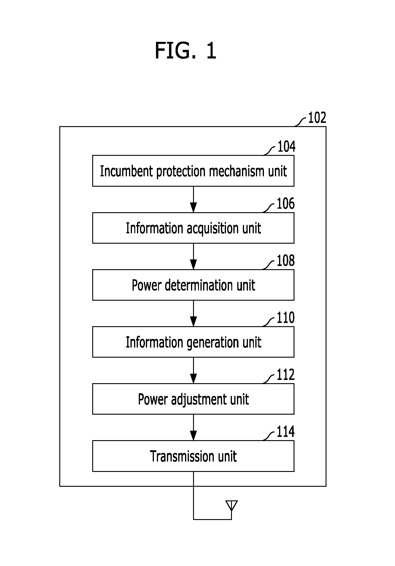
[0041]FIG. 1 illustrates a method for controlling the transmit power of a CR device in accordance with a first embodiment of the present invention.
[0042]Referring to FIG. 1, a CR device 102 includes an incumbent protection mechanism unit 104, an information acquisition unit 106, a power determination unit 108, an information generation unit 110, a power adjustment unit 112, and a transmission unit 114.
[0043]The incumbent protection mechanism unit 104 is configured to perform an incumbent protection mechanism, specifically at least one of a geolocation function, a database function, a spectrum sensing function, and a cognition pilot channel function, and acquire CR environment information. The CR environment information includes at least one of user existence / nonexistence information, user type information, user number information, and user frequency position information.
[0044]The information acquisition unit 106 is configured to acquire CR environment information from the incumbent ...
second embodiment
[0049]FIG. 2 illustrates a method for controlling the transmit power of a CR device in accordance with a second embodiment of the present invention.
[0050]Referring to FIG. 2, the CR device 202 includes an information acquisition unit 204, a power determination unit 206, an information generation unit 208, a power adjustment unit 210, and a transmission unit 212. The functionality of the acquisition unit 204, the power determination unit 206, the information generation unit 208, the power adjustment unit 210, and the transmission unit 212 of the CR device 202 is the same as that of the information acquisition unit 106, the power determination unit 108, the information generation unit 110, the power adjustment unit 112, and the transmission unit 114 of the CR device 102 illustrated in FIG. 1, and repeated description thereof will be omitted herein.
[0051]It is to be noted, however, that the CR device 202 illustrated in FIG. 2 has no incumbent protection mechanism function, unlike the C...
third embodiment
[0053]FIG. 3 illustrates a method for controlling the transmit power of a CR device in accordance with a third embodiment of the present invention.
[0054]Referring to FIG. 3, the CR device 302 includes a power adjustment unit 304 and a transmission unit 306. The CR device 302 is configured to receive transmit power control information from another device 308, which includes an incumbent protection mechanism unit 310, an information acquisition unit 312, a power determination unit 314, and an information generation unit 316, and adjust the transmit power using the transmit power control information.
[0055]The device 308 is configured to acquire CR environment information through the incumbent protection mechanism unit 310 and transfer the information to the information acquisition unit 312. The power determination unit 314 is configured to determine a transmit power value of the CR device 302 using the CR environment information transferred by the information acquisition unit 312. The ...
PUM
 Abstract
Description
Claims
Application Information
 - R&D Engineer
- R&D Manager
- IP Professional
- Industry Leading Data Capabilities
- Powerful AI technology
- Patent DNA Extraction
Browse by: Latest US Patents, China's latest patents, Technical Efficacy Thesaurus, Application Domain, Technology Topic, Popular Technical Reports.
© 2024 PatSnap. All rights reserved.Legal|Privacy policy|Modern Slavery Act Transparency Statement|Sitemap|About US| Contact US: help@patsnap.com


