
Slide core-pulling delayed mechanism and mould with the same

a technology of delayed mechanism and slide, which is applied in the field of injection moulds, can solve the problems that the conditional core-pulling mechanism cannot solve the above question completely, and achieve the effect of avoiding giving a harmful effect on the produ

Inactive Publication Date: 2012-04-26
CHENG UEI PRECISION IND CO LTD
View PDF0 Cites 28 Cited by
  • Summary
  • Abstract
  • Description
  • Claims
  • Application Information

AI Technical Summary

Benefits of technology

[0007]An object of the present invention is to provide a slide core-pulling delayed mechanism for efficiently controlling the precedence of core-pulling actions of the cavity insert and the slide insert.
[0011]Based on the above description, the mould of the present invention employs the slide core-pulling delayed mechanism. During the dismoulding process, when the cavity plate initially starts to be lifted upward, the slide base has no movement and the slide insert cannot perform the core-pulling action. When the cavity plate is lifted up to a determined distance, the slide base just starts to transversely move outward, thereby making the core-pulling action of the slide insert be performed. Therefore the core-pulling actions of the cavity plate and the slide insert of the present invention can not be interfered each other for making the dismoulding process be successfully completed and avoiding giving a harmful effect on the product.

Problems solved by technology

But the conditional core-pulling mechanism still cannot completely solve the above question.

Method used


Image

  • Slide core-pulling delayed mechanism and mould with the same
  • Slide core-pulling delayed mechanism and mould with the same
  • Slide core-pulling delayed mechanism and mould with the same

Examples


Embodiment Construction

[0026]The following embodiment with reference to the accompanying drawings now has been given for detail describing the technology, the feature, the object and the effect of the present invention.

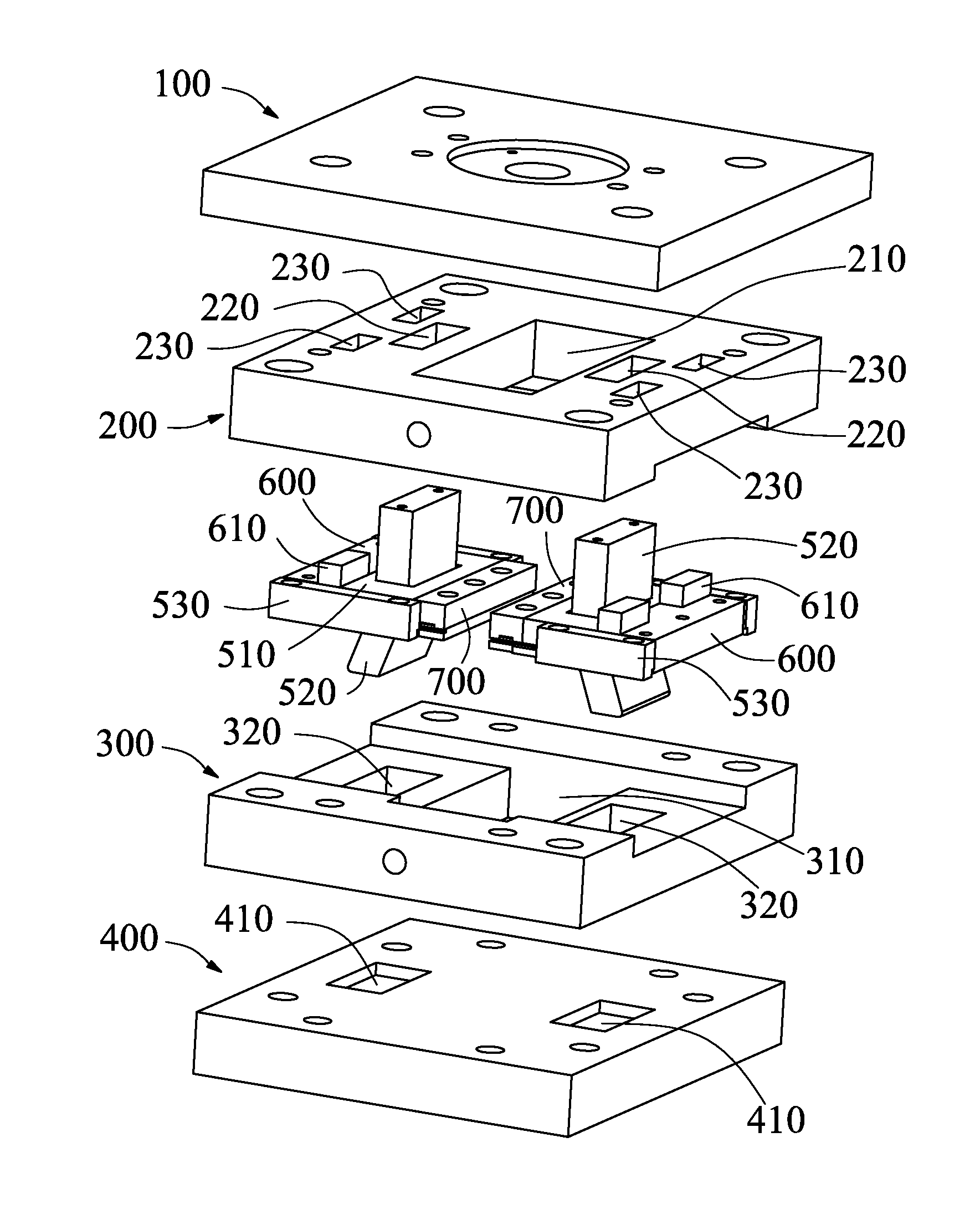
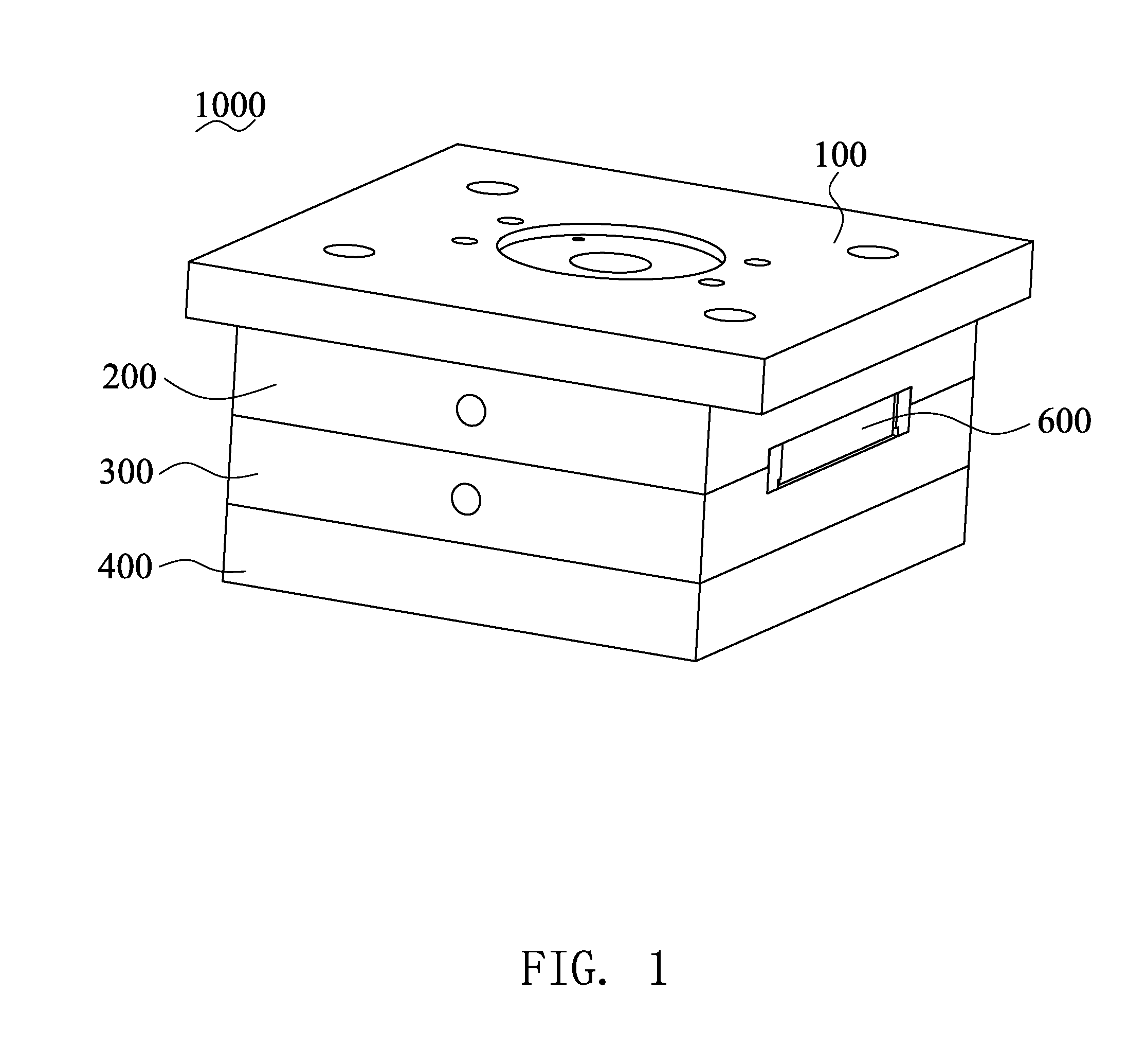
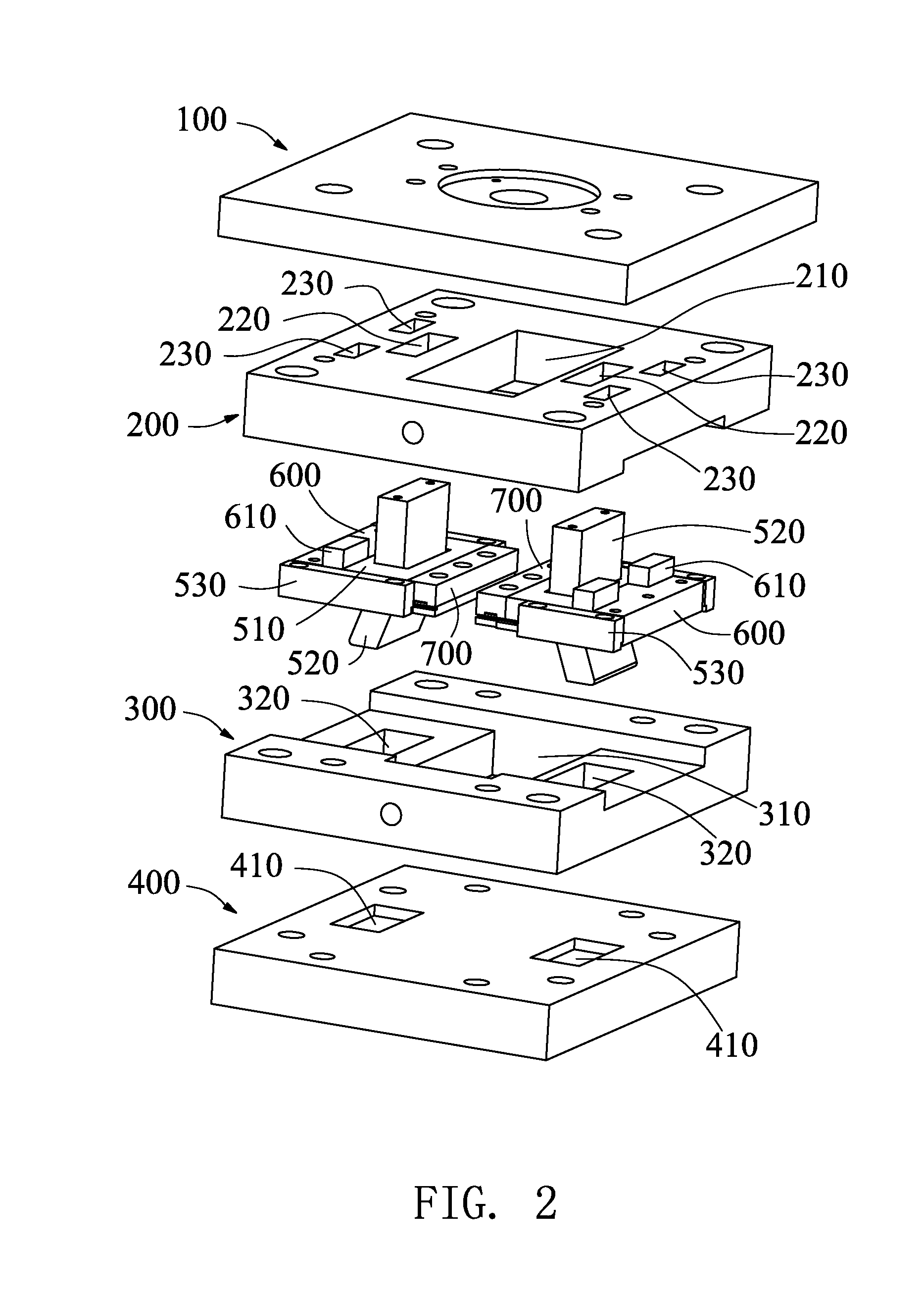
[0027]Please refer to FIGS. 1, 2 and 3, a mould 1000 of the present invention comprises a top clamping plate 100, a cavity plate 200, a core plate 300, a supporting plate 400, two slide core-pulling delayed mechanisms 500 located between the cavity plate 200 and the core plate 300, a scraping member 600, and a slide insert 700. The cavity plate 200 is connected to the top clamping plate 100. The core plate 300 is connected to the supporting plate 400. In this embodiment, the cavity plate 200 and the top clamping plate 100 are fixedly connected by bolts, and the core plate 300 is connected to the supporting plate 400 are also fixedly connected by bolts.

[0028]The cavity plate 200 disposes an upper mould cavity 210 on the middle thereof, at least two first through holes 220 separately located ...


PUM

PropertyMeasurementUnit
Angleaaaaaaaaaa
Widthaaaaaaaaaa

Abstract

Provided are a slide core-pulling delayed mechanism and a mould with the same. The slide core-pulling delayed mechanism includes a slide base, a core-pulling guide block and two slide-guiding rails. The two slide-guiding rails are parallel to each other. The slide base is slidably connected to the two slide-guiding rails. The core-pulling guide block has a vertical portion and a tilted portion. The slide base disposes a sliding hole corresponding to the core-pulling guide block. The sliding hole has a first vertical wall, a first tilted wall, a second tilted wall and a second vertical wall. The core-pulling guide block is slidably inserted into the sliding hole. During the dismoulding process, the core-pulling actions of the cavity plate and the slide insert can not be interfered each other for making the dismoulding process be successfully completed and avoiding giving a harmful effect on the product.

Description

BACKGROUND OF THE INVENTION[0001]1. Field of the Invention[0002]The present invention relates to an injection mould, and more particularly to a slide core-pulling delayed mechanism and a mould with the same.[0003]2. Description of the Prior Art[0004]With the popularization of plastic products, an injection mould is used more and more widely. The core-pulling process is absolutely necessary in producing many injection products, and can influence the quality of the products and the production efficiency. At present, core-pulling modes includes vertical core-pulling mode, side core-pulling mode and so on.[0005]However, when the finished product disposes a hole formed by a slide block, and when a cavity insert and a slide insert are inserted into each other, the cavity insert and the slide insert need perform the core-pulling action in order of precedence for avoiding interference each other and assuring the product quality. But the conditional core-pulling mechanism still cannot comple...

Claims


Application Information

Patent Timeline
IPC IPC(8): B29C45/44B29C45/36
CPCB29C45/332
Inventor WU, XIAO-PINGCAI, GANG-FUHO, SHIH-HSIUNGCHIANG, KUN-HSUEH
Owner CHENG UEI PRECISION IND CO LTD
Learn More