Grid for radiography and manufacturing method thereof, and radiation imaging system
a radiography and radiation imaging technology, applied in the direction of imaging devices, instruments, material analysis using wave/particle radiation, etc., can solve the problems of grid performance degradation x-ray absorption loss still occurring with resin use, etc., to improve the contrast of fringe images, and reduce radiation absorption loss
- Summary
- Abstract
- Description
- Claims
- Application Information
AI Technical Summary
Benefits of technology
Problems solved by technology
Method used
Image
Examples
first embodiment
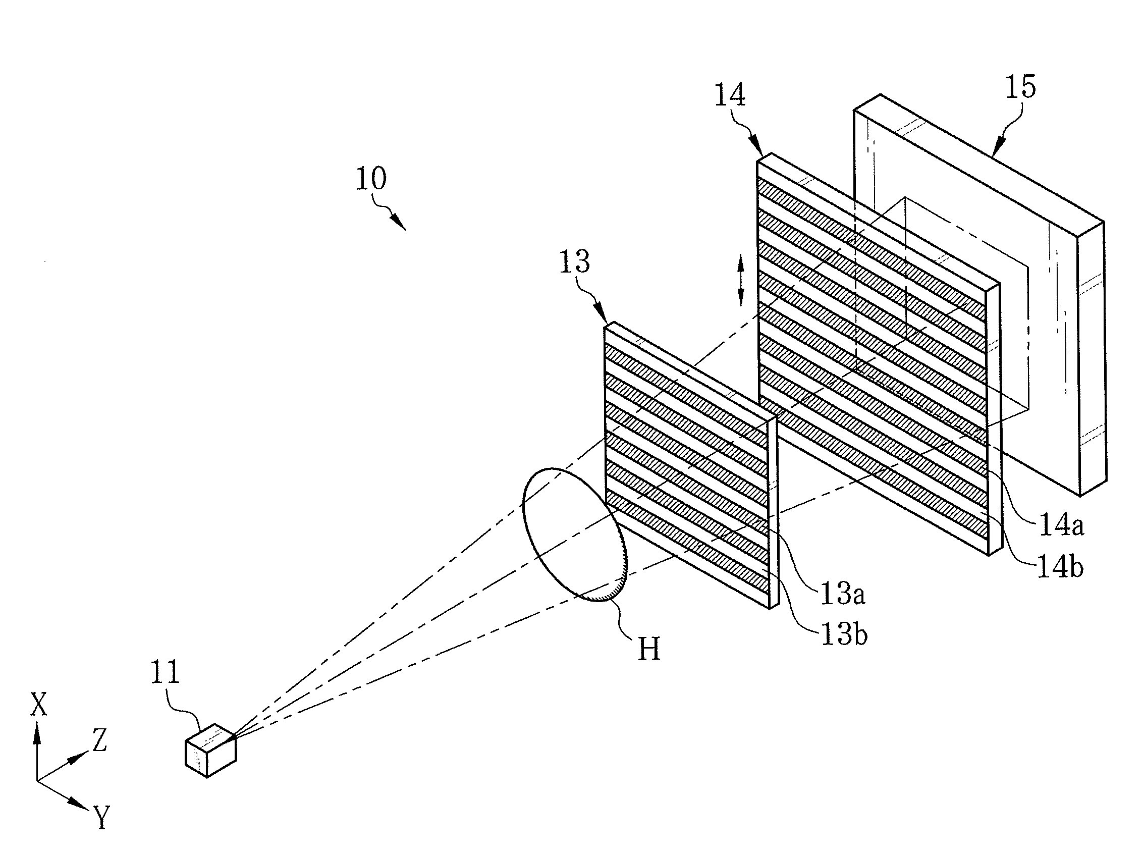
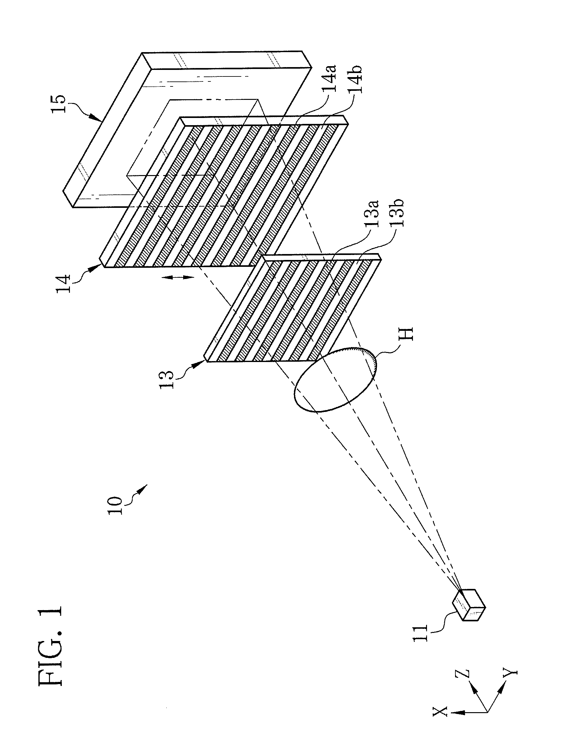
[0034]As shown in FIG. 1, an X-ray imaging system 10 is constituted of an X-ray source 11, a first grid 13, a second grid 14, and an X-ray image detector 15. The X-ray source 11 has a rotation-anode type X-ray tube and a collimator for limiting an irradiation field of X-rays, for example, and applies the X-rays to a sample H. The first and second grids 13 and 14, being of an X-ray absorptive type, are opposed to the X-ray source 11 in a Z direction corresponding to an X-ray propagation direction. The first grid 13 is disposed at a certain distance away from the X-ray source 11 so as to place the sample H therebetweeen. The X-ray image detector 15 is a flat panel detector (FPD) composed of semiconductor circuitry, for example, and is disposed behind the second grid 14.
[0035]The first grid 13 is provided with plural X-ray absorbing portions 13a and X-ray transparent portions 13b, which extend in a Y direction being one direction in a plane orthogonal to the Z direction. The X-ray abso...
second embodiment
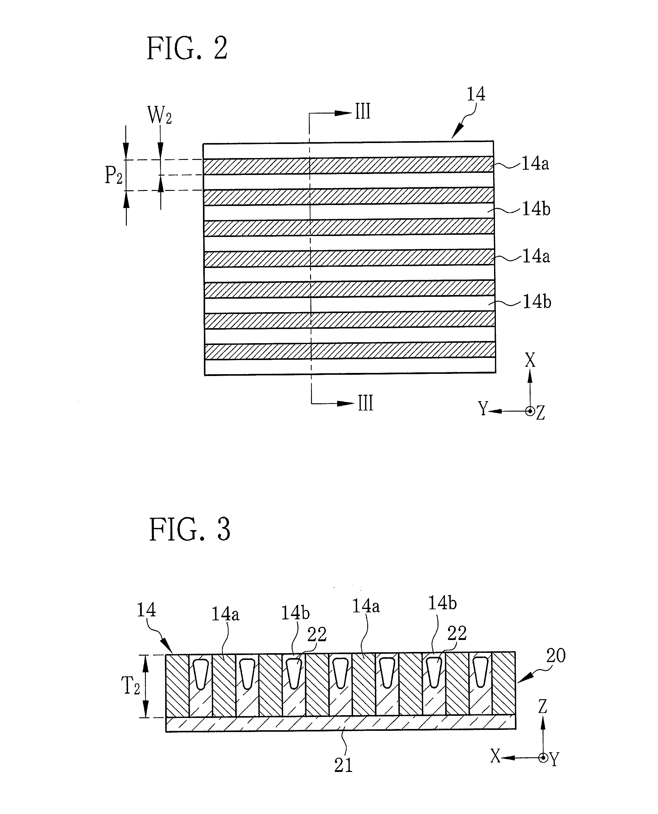
[0055]FIG. 13 shows a cross section of a second grid 40 according to this embodiment taken along the XZ plane. The second grid 40 includes a grid layer 41 and the support member 21. The grid layer 41 has the X-ray absorbing portions 14a and the X-ray transparent portions 14b arranged alternately in the X direction, and a reinforcing layer 42 formed between the X-ray absorbing portion 14a and the X-ray transparent portion 14b. The reinforcing layer 42 is formed between the X-ray absorbing portion 14a and the support member 21.
[0056]The reinforcing layer 42 is preferably formed of a material with high X-ray transparency and high stiffness, for example, SiO2. In a case where the X-ray transparent portions 14b are made of the organic material such as resin, there is a possibility of deformation of the X-ray transparent portions 14b. The reinforcing layer 42 has the high stiffness enough to maintain the shape of the X-ray transparent portions 14b and prevent the deformation thereof. Also...
third embodiment
[0058]FIG. 14 shows a cross section of a second grid 50 according to this embodiment taken along the XZ plane. The second grid 50 has a grid layer 51 and a support member 52. The grid layer 51 is constituted of the X-ray absorbing portions 14a and X-ray transparent portions 53 arranged alternately in the X direction. The X-ray transparent portions 53 and the support member 52 are made of a resin paste with high X-ray transparency. As the resin paste, for example, an acrylic resin having air bubbles 53a dispersed therein is used.
[0059]To manufacture the second grid 50, in the sixth step shown in FIG. 9 of the manufacturing process of the second grid 14 according to the first embodiment, the resin paste containing the air bubbles 53a may be charged into the grooves 35 and dried therein, instead of depositing the X-ray transparent material 36 in the grooves 35 by the CVD. The resin paste is produced by dispersing a resin material in a solvent. Then, to form the air bubbles 53a, the res...
PUM
| Property | Measurement | Unit |
|---|---|---|
| thickness | aaaaa | aaaaa |
| width W2 | aaaaa | aaaaa |
| width W2 | aaaaa | aaaaa |
Abstract
Description
Claims
Application Information
 - Generate Ideas
- Intellectual Property
- Life Sciences
- Materials
- Tech Scout
- Unparalleled Data Quality
- Higher Quality Content
- 60% Fewer Hallucinations
Browse by: Latest US Patents, China's latest patents, Technical Efficacy Thesaurus, Application Domain, Technology Topic, Popular Technical Reports.
© 2025 PatSnap. All rights reserved.Legal|Privacy policy|Modern Slavery Act Transparency Statement|Sitemap|About US| Contact US: help@patsnap.com


