
Display device

a display device and display technology, applied in the field of display devices, can solve the problems of attracting much attention, limiting the development of limitations in slimming display devices and developing new designs of display devices, so as to achieve the effect of reducing the thickness of display devices or changing the design

Active Publication Date: 2012-04-26
LG DISPLAY CO LTD
View PDF9 Cites 12 Cited by
  • Summary
  • Abstract
  • Description
  • Claims
  • Application Information

AI Technical Summary

Benefits of technology

The present invention provides a display device that solves problems of the related art. The display device includes a display panel that is exposed in the front surface of the device, and a guide frame that is joined to the rear surface of the display panel with an adhesive member. The device also includes a panel driver placed inside the rear set cover, and a lower finishing material that supports the panel. The technical effects of the invention include improved display quality, reduced thickness, and improved durability.

Problems solved by technology

However, LCDs are easily manufactured, have drivability of drivers, realize a high-quality image, and thus are attracting much attention.
Due to these reasons, there are limitations in slimming display devices and developing the new designs of the display devices.
As described above, display devices of the related art essentially include the front set cover and rear set cover, and consequently, there are limitations in reducing the thicknesses of LCD devices or changing the designs thereof.
Consequently, the thicknesses of display devices inevitably become thicker, and moreover, the border widths of the display devices enlarge.
In addition, it is difficult to realize various innovative designs due to a step height in a border portion.
However, in the related art borderless display device, the tampered glass 50 covers the entire front, and thus, scratch occurs due to friction between the tampered glass 50 and the display device 10, causing the deterioration of brightness.
Furthermore, touch occurs in a gap between the lower surface of the tampered glass 50 and the upper surface of the liquid crystal panel 11, causing scratch.

Method used


Image

  • Display device
  • Display device
  • Display device

Examples


first embodiment

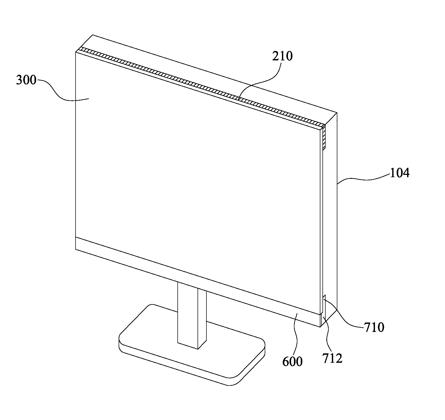
[0033]FIG. 2 is a sectional view illustrating a display device according to the present invention. FIG. 3 is an exemplary view illustrating an adhesive member applied to embodiments of the present invention.

[0034]The display device according to the first embodiment of the present invention includes a rear set cover 100, an upper end guide frame 200, a panel 300, a panel driver 400, a first adhesive member 500, a lower finishing material 600, a lower end guide frame 700, and a second adhesive member 800.

[0035]The rear set cover 100 covers the outermost portion of a rear surface of the display device, and includes a rear set plate 104, a rear set inner wall 102, and a rear set coupling part 106.

[0036]The rear set plate 104 forms the outer appearance of the rear set cover 100, and may be formed in a rectangular shape. Alternatively, as illustrated in FIG. 2, the rear set plate 104 may be formed to have both rounded ends.

[0037]The rear set inner wall 102 is a plate that protrudes toward...

second embodiment

[0086]In the present invention, the upper end panel guide 212 that is bent from the upper end guide frame 200 is bent in a direction opposite to the upper end guide side coupling member 210, namely, a panel direction and thus guides and protects the upper side of the panel 300. The upper end panel guide may be coupled to the upper side of the panel 300 with the third adhesive member 900.

[0087]The upper end panel guide 212 surrounds the panel 300 along only the upper side of the panel 300, and thus, a stepped portion is not formed between the upper end panel guide 212 and the front surface of the panel 300 when seen from the front of the panel 300.

[0088]According to embodiments of the present invention, the display panel is exposed in the front surface of the display device, and the guide frame coupled to the rear set cover is joined to the rear surface of the display panel with the adhesive member, and thus, a front set cover is not provided.

[0089]According to embodiments of the pre...


PUM


Abstract

A display device includes a rear set cover, an upper end guide frame, a lower end guide frame, a panel, a first adhesive member, a second adhesive member, a panel driver, and a lower finishing material. The upper end guide frame is secured to an upper end portion inside the rear set cover, and coupled to the rear set cover. The lower end guide frame is secured to a lower end portion inside the rear set cover, and coupled to the rear set cover. The panel is secured to the upper end guide frame and lower end guide frame. The first adhesive member couples the upper end guide frame and panel. The second adhesive member couples the lower end guide frame and panel. The panel driver is placed inside the rear set cover, and drives the panel.

Description

CROSS REFERENCE TO RELATED APPLICATIONS[0001]This application claims the benefit of the Korean Patent Application No. 10-2010-0103993 filed on Oct. 25, 2010, which is hereby incorporated by reference as if fully set forth herein.BACKGROUND[0002]1. Field of the Invention[0003]The present invention relates to a display device, and more particularly, to a display device, which has a minimized thickness by removing a portion of a case that was regarded as an essential element in producing the display device, and leads to the enhancement of a sense of beauty by applying an innovative design.[0004]2. Discussion of the Related Art[0005]Recently, Flat Panel Display (FPD) devices that can decrease a weight and a volume corresponding to the limitations of Cathode Ray Tubes (CRTs) are being developed. Liquid Crystal Display (LCD) devices, Plasma Display Panels (PDPs), Field Emission Display (FED) devices, and light emitting display devices are actively being researched as FPD devices. However,...

Claims


Application Information

Patent Timeline
Patent Type & Authority Applications(United States)
IPC IPC(8): H05K7/00
CPCG06F1/1637G06F1/1601H04N5/64H04N5/655
Inventor PARK, SANGRYEON
Owner LG DISPLAY CO LTD
Learn More